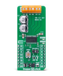
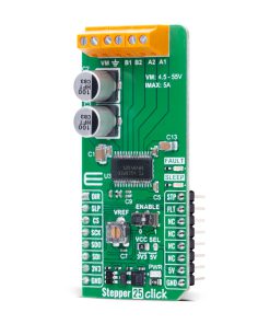
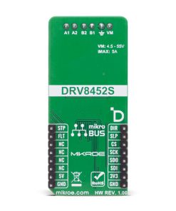
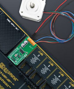
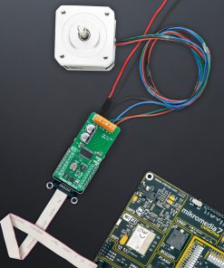
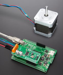
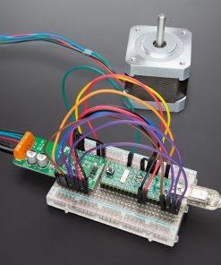
Stepper 25 Click is a compact add-on board designed for precise control of bipolar stepper motors. This board features the DRV8452, a high-power stepper motor driver from Texas Instruments, known for its high performance and integration. The board supports a wide supply voltage range from 4.5V to 55V and delivers up to 5A full-scale or 3.5A RMS output current. It features advanced microstepping down to 1/256, auto-torque adjustment for improved efficiency, stall detection, smart tune decay modes, and integrated current sensing. Stepper 25 Click is ideal for applications such as textile machines, factory automation, robotics, diagnostic equipment, multifunction printers, and industrial control systems.
Stepper 25 Click is fully compatible with the mikroBUS™ socket and can be used on any host system supporting the mikroBUS™ standard. It comes with the mikroSDK open-source libraries, offering unparalleled flexibility for evaluation and customization. What sets this Click board™ apart is the groundbreaking ClickID feature, enabling your host system to seamlessly and automatically detect and identify this add-on board.
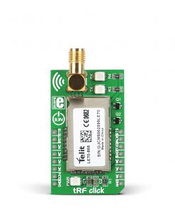 tRF Click
1 × R1,050.00
tRF Click
1 × R1,050.00 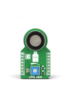 LPG Click
1 × R325.00
LPG Click
1 × R325.00 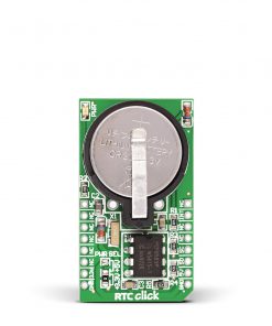 RTC Click
1 × R380.00
RTC Click
1 × R380.00 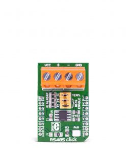 RS485 Click 5V
1 × R230.00
RS485 Click 5V
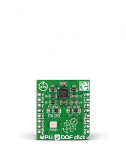
1 × R230.00 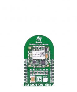 3D Motion Click
1 × R1,050.00
3D Motion Click
1 × R1,050.00  EXPAND Click
1 × R255.00
EXPAND Click
1 × R255.00 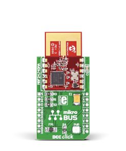 BEE Click
1 × R780.00
BEE Click
1 × R780.00