-
×
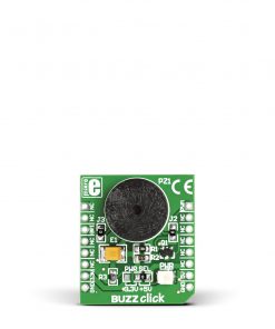 BUZZ Click
1 × R115.00
BUZZ Click
1 × R115.00
Subtotal: R115.00


R530.00 ex. VAT
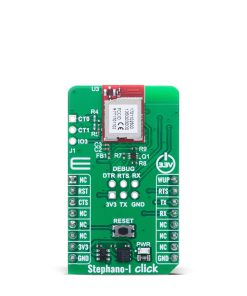
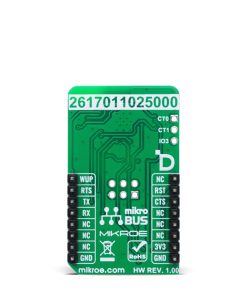
Stephano-I Click is a compact add-on board designed to add WiFi and Bluetooth® LE connectivity to any embedded system. This board features the Stephano-I (2617011025000) radio module from Würth Elektronik. The module supports IEEE 802.11 b/g/n WiFi in the 2.4GHz band and Bluetooth® LE 5 in both peripheral and central roles, offering dual radio support with a simple AT command interface over UART. It features a 1Mbps data rate, WiFi output power up to 13.4dBm, and Bluetooth® LE output power up to 4.5dBm. The board includes standard UART communication pins, hardware flow control, reset and wake-up options, and additional unpopulated debug and boot control pins for advanced functionality. Ideal for IoT, smart home, and industrial applications, Stephano-I Click enables low-power wireless communication with smart devices and cloud services.
Stephano-I Click is fully compatible with the mikroBUS™ socket and can be used on any host system supporting the mikroBUS™ standard. It comes with the mikroSDK open-source libraries, offering unparalleled flexibility for evaluation and customization. What sets this Click board™ apart is the groundbreaking ClickID feature, enabling your host system to seamlessly and automatically detect and identify this add-on board.
Stock: Lead-time applicable.
| 5+ | R503.50 |
| 10+ | R477.00 |
| 15+ | R450.50 |
| 20+ | R433.54 |
Stephano-I Click is based on the Stephano-I (2617011025000) radio module from Würth Elektronik. Designed for WiFi and Bluetooth® LE functionalities, this module supports IEEE 802.11 b/g/n standards in the 2.4GHz band and features both peripheral and central roles for Bluetooth® LE 5, ensuring reliable low-power communication with a wide range of smart devices. Its dual radio support, combined with a straightforward AT-style command interface over UART, makes it an excellent choice for various wireless IoT applications. With a data rate of 1Mbps, the WiFi interface delivers a maximum output power of 13.4dBm and a sensitivity of -87dBm across a frequency range of 2412 to 2484MHz, while the Bluetooth® LE interface offers a maximum output power of 4.5dBm, sensitivity of -89dBm, and operates between 2402 and 2480MHz.

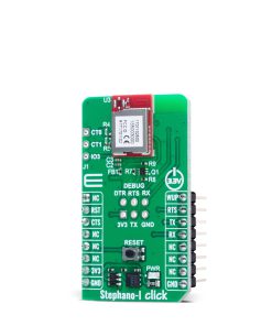
Communication between the Stephano-I (2617011025000) module and the host MCU is established through a UART interface, standard UART RX and TX pins, and hardware flow control pins (CTS/RTS). The default communication speed is 115200bps, ensuring efficient data exchange. It can be easily configured using AT commands, after which it autonomously manages radio connectivity – freeing up valuable processing resources on the host system. In addition to the interface pins, the board features a reset (RST) pin and a RESET button for hard resetting the module when necessary, as well as the WUP pin used as trigger to wake-up from sleep mode. In addition, Stephano-I Click features several unpopulated pins on the board, offering expanded functionality for advanced users.
A dedicated group of these pins, labeled DEBUG, serves as an optional debug UART interface and flash control specifically intended for end device certification processes. The debug UART interface on the Stephano-I module allows developers to load test firmware and manage various test modes during development and validation. Alongside these debug pins, another group of unpopulated pins provides access to boot control functions, including CT0 and CT1 pins, which are used to trigger the bootloader mode for firmware updates when set to the appropriate logic level during reset. Also included in this set is the IO3 pin, a general-purpose I/O line that can be configured either as a wake-up source or used as an analog input through its ADC functionality, further extending the flexibility of the module in power-sensitive and data acquisition applications.
This Click board™ can be operated only with a 3.3V logic voltage level. The board must perform appropriate logic voltage level conversion before using MCUs with different logic levels. It also comes equipped with a library containing functions and example code that can be used as a reference for further development.
Type
WiFi+BLE
Applications
Ideal for IoT, smart home, and industrial applications
On-board modules
Stephano-I (2617011025000) – WiFi and Bluetooth® LE 5 radio module from Würth Elektronik
Key Features
Dual radio support, UART interface with AT command set, debug UART and boot control, general-purpose IO with ADC function, 2.4GHz operation, integrated WiFi and BLE stack, low power consumption, firmware update support via bootloader mode, and more
Interface
UART
Feature
ClickID
Compatibility
mikroBUS™
Click board size
M (42.9 x 25.4 mm)
Input Voltage
3.3V
This table shows how the pinout on Stephano-I Click corresponds to the pinout on the mikroBUS™ socket (the latter shown in the two middle columns).
| Notes | Pin | Pin | Notes | ||||
|---|---|---|---|---|---|---|---|
| NC | 1 | AN | PWM | 16 | WUP | Sleep Mode Wake-Up | |
| Reset / ID SEL | RST | 2 | RST | INT | 15 | RTS | UART RTS |
| UART CTS / ID COMM | CTS | 3 | CS | RX | 14 | TX | UART TX |
| NC | 4 | SCK | TX | 13 | RX | UART RX | |
| NC | 5 | MISO | SCL | 12 | NC | ||
| NC | 6 | MOSI | SDA | 11 | NC | ||
| Power Supply | 3.3V | 7 | 3.3V | 5V | 10 | NC | |
| Ground | GND | 8 | GND | GND | 9 | GND | Ground |
| Label | Name | Default | Description |
|---|---|---|---|
| LD1 | PWR | – | Power LED Indicator |
| T1 | RESET | – | Reset Button |
| Description | Min | Typ | Max | Unit |
|---|---|---|---|---|
| Supply Voltage | – | 3.3 | – | V |
| WiFi Frequency Range | 2412 | – | 2484 | MHz |
| WiFi Output Power | – | 13.4 | – | dBm |
| WiFi Sensitivity | – | -87 | – | dBm |
| Bluetooth Frequency Range | 2402 | – | 2480 | MHz |
| Bluetooth Sensitivity | – | -89 | – | dBm |
| Bluetooth Output Power | – | 4.5 | – | dBm |
| Data Rate | – | – | 1 | Mbps |
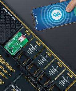
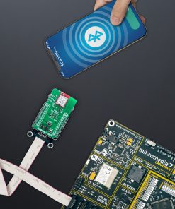
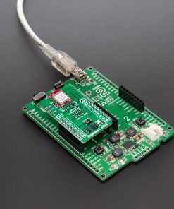
Stephano-I Click demo application is developed using the NECTO Studio, ensuring compatibility with mikroSDK‘s open-source libraries and tools. Designed for plug-and-play implementation and testing, the demo is fully compatible with all development, starter, and mikromedia boards featuring a mikroBUS™ socket.
Example Description
Application example shows device capability of connecting to a WiFi network and sending TCP/UDP messages to an echo server, or processing data from a connected BLE device.
Key Functions
stephanoi_cfg_setup This function initializes Click configuration structure to initial values.stephanoi_init This function initializes all necessary pins and peripherals used for this Click board.stephanoi_cmd_run This function sends a specified command to the Click module.stephanoi_cmd_set This function sets a value to a specified command of the Click module.stephanoi_cmd_get This function is used to get the value of a given command from the Click module.Application Init
Initializes the driver and logger.
Application Task
Application task is split in few stages:
Powers up the device, performs a factory reset and reads system information.
Configures connection to WiFi or BLE depending on the selected example.
Depending on the selected demo example, it sends a TCP/UDP message to an echo server over a WiFi network or processes all data from a connected BLE device and sends back an adequate response message.
By default, the WiFi TCP/UDP example is selected.
Application Output
This Click board can be interfaced and monitored in two ways:
Additional Notes and Information
The complete application code and a ready-to-use project are available through the NECTO Studio Package Manager for direct installation in the NECTO Studio. The application code can also be found on the MIKROE GitHub account.
| Weight | 17 g |
|---|---|
| Brand | MikroElektronika |