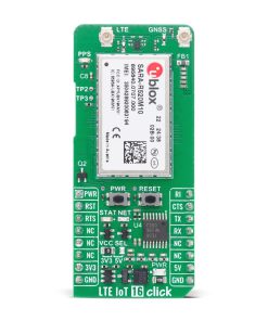
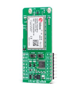
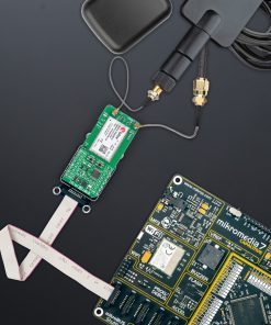
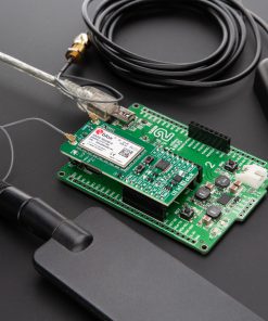
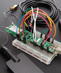
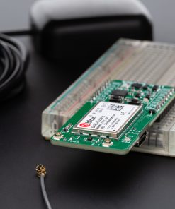
LTE IoT 16 Click is a compact add-on board designed for cellular connectivity and GNSS-based positioning in IoT applications. This board features the SARA-R520M10 module from u-blox, part of the SARA-R52 series. Supporting LTE Cat M1 and NB2 across multiple global bands, it combines low power consumption with enhanced data rates and integrated u-blox M10 GNSS for accurate location tracking. The board features UART and USB interfaces, power and reset control, dual antenna support, micro SIM compatibility, and robust security features including secure boot and cloud service certifications. Ideal for asset tracking, smart metering, remote monitoring, and location-based services.
LTE IoT 16 Click is fully compatible with the mikroBUS™ socket and can be used on any host system supporting the mikroBUS™ standard. It comes with the mikroSDK open-source libraries, offering unparalleled flexibility for evaluation and customization. What sets this Click board™ apart is the groundbreaking ClickID feature, enabling your host system to seamlessly and automatically detect and identify this add-on board.
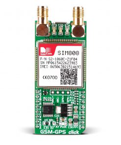 GSM-GPS Click
1 × R1,300.00
GSM-GPS Click
1 × R1,300.00 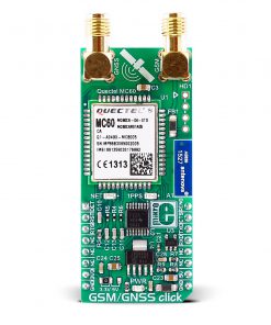 GSM/GNSS Click
1 × R1,650.00
GSM/GNSS Click
1 × R1,650.00  RTC 2 Click
1 × R455.00
RTC 2 Click
1 × R455.00  DAC Click
2 × R400.00
DAC Click
2 × R400.00  NFC Extend Click
1 × R125.00
NFC Extend Click
1 × R125.00