-
×
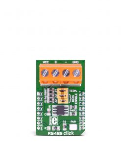 RS485 Click 5V
1 × R230.00
RS485 Click 5V
1 × R230.00
Subtotal: R230.00


R275.00 ex. VAT
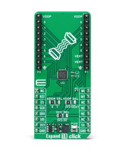
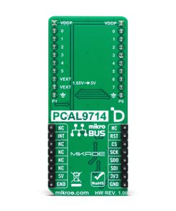
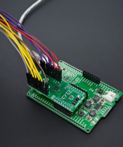
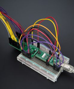
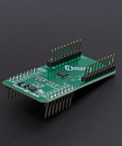
Expand 18 Click is a compact add-on board used for expanding the I/O capabilities of various microcontroller (MCU) systems. This board features the PCAL9714, an ultra-low-voltage 14-bit SPI I/O expander from NXP. This board supports both 3.3V and 5V logic levels, features integrated level shifting for mixed-voltage systems, and operates via a high-speed 5MHz SPI interface. Additionally, it offers Agile I/O capabilities such as programmable output drive strength, latchable inputs, and interrupt management. Expand 18 Click is ideal for interfacing MCUs with sensors, keypads, and push buttons in power-sensitive applications.
Expand 18 Click is fully compatible with the mikroBUS™ socket and can be used on any host system supporting the mikroBUS™ standard. It comes with the mikroSDK open-source libraries, offering unparalleled flexibility for evaluation and customization. What sets this Click board™ apart is the groundbreaking ClickID feature, enabling your host system to seamlessly and automatically detect and identify this add-on board.
Stock: Lead-time applicable.
| 5+ | R261.25 |
| 10+ | R247.50 |
| 15+ | R233.75 |
| 20+ | R224.95 |
Expand 18 Click is based on the PCAL9714, an ultra low-voltage translating 14-bit SPI I/O expander from NXP. This board enables I/O expansion for a wide range of microcontroller (MCU) families, offering additional GPIO (General Purpose Input/Output) pins with minimal interconnection requirements. It operates via the SPI interface, making it compatible with various MCUs. Its ultra-low voltage interface supports direct communication with MCUs operating at voltages as low as 1.1V, while simultaneously interfacing with I/O devices at different voltage levels. This I/O expanding solution is particularly suited for tasks that require interfacing with sensors, push buttons, keypads, and other input devices, all while ensuring that power consumption and pin usage are kept to a minimum.

The PCAL9714 used in Expand 18 Click features an integrated level-shifting capability, providing exceptional flexibility in systems with mixed power supplies. It operates with two distinct power supplies: one for its logic side and one for its core circuits. The logic side can be powered by either the 3.3V or 5V mikroBUS™ power rails, selectable via the VCC SEL jumper. The core circuits, however, can draw power either from the 3.3V mikroBUS™ rail or an external power source connected to the VEXT pins, supporting voltages from 1.65V to 5V. This core circuit power source is adjustable via the VDDP SEL jumper, ensuring optimal voltage management for diverse application needs.
Expand 18 Click communicates with the host MCU via a 4-wire SPI interface, supporting a maximum clock frequency of 5MHz, ensuring efficient and reliable data transfer. In addition to the SPI interface, the board includes an active-low RST pin to reset the PCAL9714 in case of time-outs or operational issues. The power-on reset restores the registers to their default state and reinitializes the SPI state machine, while the RST pin allows the same reset process without requiring a complete power cycle.
The PCAL9714 also incorporates Agile I/O features, enhancing the functionality of the I/Os. These features include programmable output drive strength, latchable inputs, programmable pull-up and pull-down resistors, maskable interrupts, an interrupt status register, and configurable open-drain or push-pull outputs. Additionally, Agile I/O Plus offers interrupts specified by level or edge, with the ability to clear them individually without affecting other events. The interrupt (INT) pin is triggered when an input state changes from its corresponding Input Port register state, alerting the host MCU of the change.
At power-on, all I/Os are configured as inputs. However, the host MCU can easily reconfigure them as either inputs or outputs by writing to the appropriate I/O configuration bits. Data for each I/O is stored in the corresponding input or output register, and the Input Port register’s polarity can be inverted through the Polarity Inversion register, eliminating the need for external logic gates. Programmable pull-up and pull-down resistors further reduce the need for discrete components.
The expander outputs offer 25mA sink capabilities, allowing for direct LED driving while maintaining low current consumption. Additionally, the PCAL9714 features a hardware pin for SPI-bus address programming, accessible via the ADDR SEL jumper, enabling up to four devices to share the same SPI bus.
This Click board™ can operate with either 3.3V or 5V logic voltage levels selected via the VCC SEL jumper. This way, both 3.3V and 5V capable MCUs can use the communication lines properly. Also, this Click board™ comes equipped with a library containing easy-to-use functions and an example code that can be used as a reference for further development.
Type
Port expander
Applications
Ideal for interfacing MCUs with sensors, keypads, and push buttons in power-sensitive applications
On-board modules
PCAL9714 – ultra-low-voltage 14-bit SPI I/O expander from NXP
Key Features
Ultra-low voltage operation, integrated level shifting, agile I/O features, multiple power supply options, 25mA sink capability, configurable interrupts, flexible GPIO configuration, SPI bus address selection, and more
Interface
SPI
Feature
ClickID
Compatibility
mikroBUS™
Click board size
L (57.15 x 25.4 mm)
Input Voltage
3.3V or 5V,External
This table shows how the pinout on Expand 18 Click corresponds to the pinout on the mikroBUS™ socket (the latter shown in the two middle columns).
| Notes | Pin | Pin | Notes | ||||
|---|---|---|---|---|---|---|---|
| NC | 1 | AN | PWM | 16 | NC | ||
| Reset / ID SEL | RST | 2 | RST | INT | 15 | INT | Interrupt |
| SPI Select / ID COMM | CS | 3 | CS | RX | 14 | NC | |
| SPI Clock | SCK | 4 | SCK | TX | 13 | NC | |
| SPI Data OUT | SDO | 5 | MISO | SCL | 12 | NC | |
| SPI Data IN | SDI | 6 | MOSI | SDA | 11 | NC | |
| Power Supply | 3.3V | 7 | 3.3V | 5V | 10 | 5V | Power Supply |
| Ground | GND | 8 | GND | GND | 9 | GND | Ground |
| Label | Name | Default | Description |
|---|---|---|---|
| LD1 | PWR | – | Power LED Indicator |
| JP1 | VCC SEL | Left | Power Voltage Level Selection 3V3/5V: Left position 3V3, Right position 5V |
| JP2 | VDDP SEL | Left | PCAL9714 Power Supply Selection 3V3/VEXT: Left position 3V3, Right position VEXT |
| JP3 | ADDR SEL | Left | SPI Address Selection 0/1: Left position 0, Right position 1 |
| Description | Min | Typ | Max | Unit |
|---|---|---|---|---|
| Supply Voltage | 3.3 | – | 5 | V |
| External Power Supply | 1.65 | – | 5 | V |
| Maximum Drive Current | – | – | 25 | mA |
We provide a library for the Expand 18 Click as well as a demo application (example), developed using MIKROE compilers. The demo can run on all the main MIKROE development boards.
Package can be downloaded/installed directly from NECTO Studio Package Manager (recommended), downloaded from our LibStock™ or found on MIKROE github account.
Library Description
This library contains API for Expand 18 Click driver.
Key functions
expand18_set_pin_direction This function sets the direction of the selected pins.
expand18_set_all_pins_value This function sets the value of all output pins.
expand18_read_port_value This function reads the value of the selected port input pins.
Example Description
This example demonstrates the use of Expand 18 Click by setting and reading the ports state.
void application_task ( void )
 {
     uint8_t port_value = 0;
     for ( uint16_t pin_num = EXPAND18_PIN_0_MASK; pin_num <= EXPAND18_PIN_7_MASK; pin_num <<= 1 )
     {
         expand18_set_all_pins_value( &expand18, pin_num );

         expand18_read_port_value( &expand18, EXPAND18_PORT_0, &port_value );
         log_printf( &logger, " Status port 0 (output): 0x%.2Xrn", ( uint16_t ) port_value );

         expand18_read_port_value( &expand18, EXPAND18_PORT_1, &port_value );
         log_printf( &logger, " Status port 1 (input) : 0x%.2Xrnn", ( uint16_t ) port_value );
         Delay_ms( 1000 );
     }
 }
The full application code, and ready to use projects can be installed directly from NECTO Studio Package Manager (recommended), downloaded from our LibStock™ or found on MIKROE github account.
Other MIKROE Libraries used in the example:
Additional notes and informations
Depending on the development board you are using, you may need USB UART click, USB UART 2 Click or RS232 Click to connect to your PC, for development systems with no UART to USB interface available on the board. UART terminal is available in all MIKROE compilers.
This Click board™ is supported with mikroSDK – MIKROE Software Development Kit. To ensure proper operation of mikroSDK compliant Click board™ demo applications, mikroSDK should be downloaded from the LibStock and installed for the compiler you are using.
For more information about mikroSDK, visit the official page.
| Weight | 20 g |
|---|---|
| Brand | MikroElektronika |