How does it work?
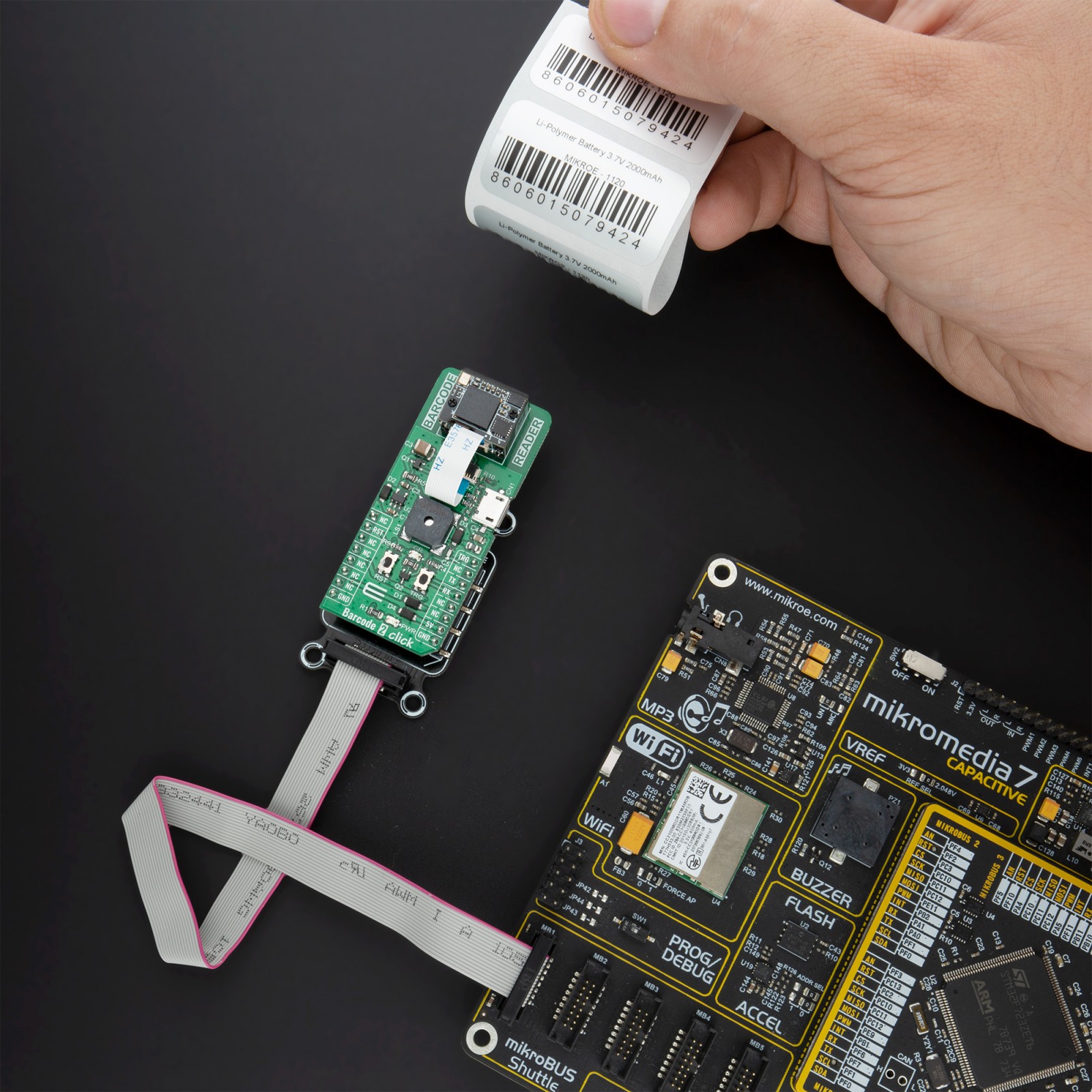
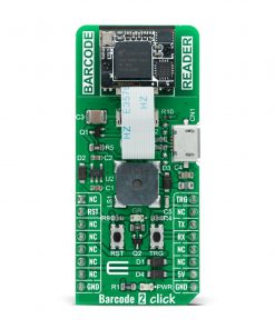
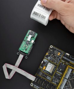
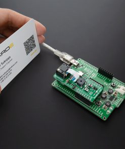
Barcode 2 Click is based on the EM3080-W, a barcode decoder chip that delivers superior performance and solid reliability with low power consumption from Newland Auto-ID Tech. Co., Ltd. This barcode scanner module is designed to quickly scan the barcode or QRcode data, and send the information either to the host MCU or the host PC. It features an excellent near-field reading, wide-viewing angle, and snappy reading, the also offers stunning performance on decoding poor-quality and damaged barcodes. The advanced technology incorporated in the EM3080-W helps reduce its power consumption and prolong its service life.
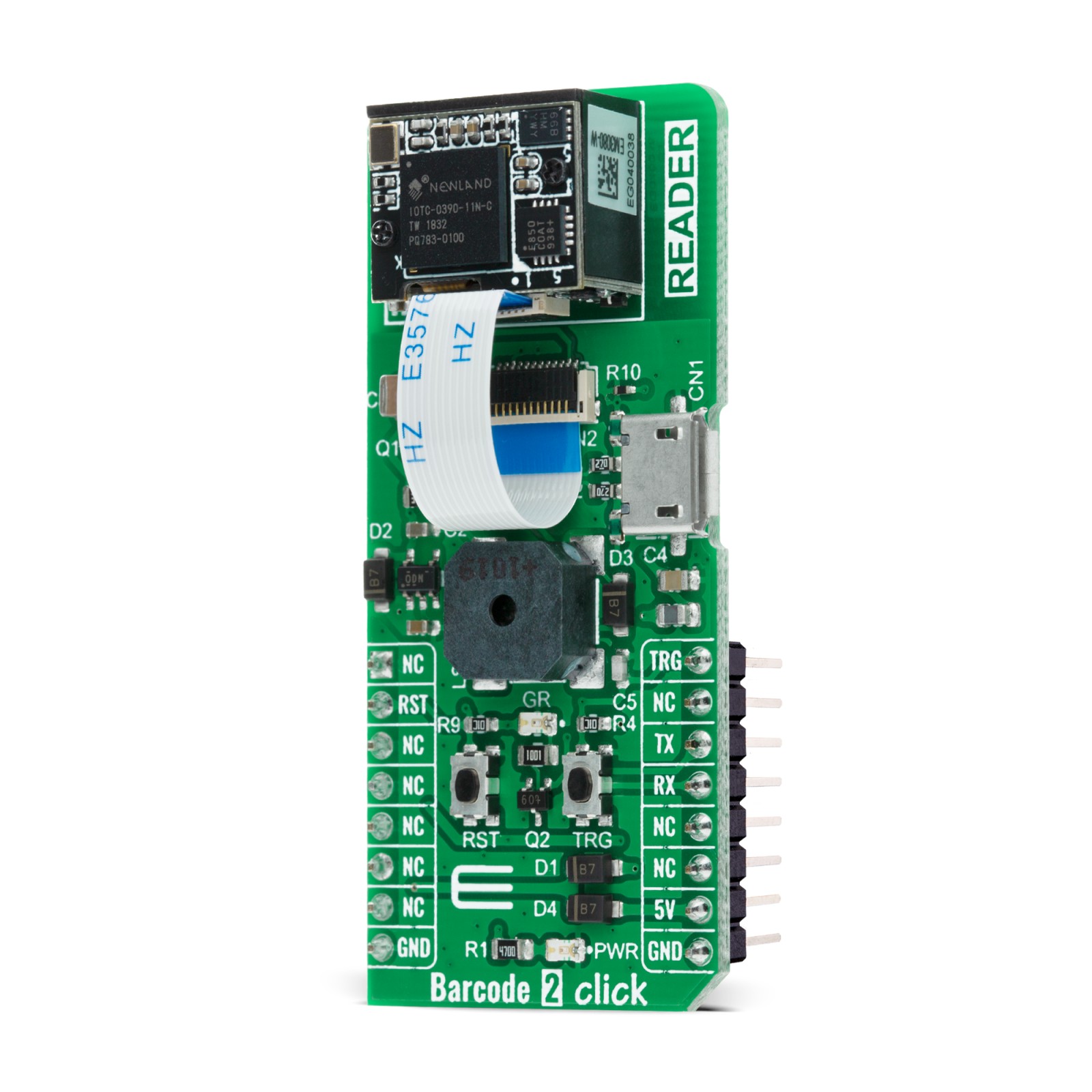
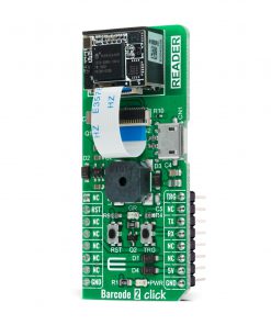
The EM3080-W scanner module uses a flat cable to connect to the Click board™, via the FPC Connector which is located on the top side of the PCB. This flat cable carries all the signals used in communication between the EM3080-W module and the host MCU, such as the RX, TX, buzzer, USB, LED, reset, and scanning trigger lines.
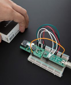
Barcode 2 Click communicates with MCU using the UART interface at 9600 bps as its default communication protocol, but it is also equipped with the micro USB port; thus, it can work both as a standalone device and a standard Click board™. When the Click board™ is placed into the mikroBUS™ socket, it will be able to exchange data via the standard mikroBUS™ RX and TX pins.
Additional functionality, Reset and Scan Trigger push-buttons, are provided and routed at RST and PWM pins of the mikroBUS™ socket labeled as RST and TRG used to control the device when working as a standalone device. Both lines alongside with the EM3080-W scanner module are powered with TLV70033DDCT, low IQ LDO, which at its output gives a voltage of 3.3 V, and which at its input can receive a 5V from mikroBUS™, or can be powered from the micro USB connector. This Click board™ also features the CMT-8540S-SMT magnetic buzzer controlled by the EM3080-W used for audible signalization and notification. You can create different sound patterns using the Sound library supported in our compilers. Signal frequency determines the sound pitch, and the duty cycle determines the amplitude (sound volume).
Pressing the onboard TRIG button or pulling the PWM pin of the mikroBUS™ to a LOW logic level for at least 10ms, will trigger the barcode scan. A short beep sound and a blink of the Barcode Detection LED Indicator (GR) will indicate a successful barcode decoding and after releasing the TRIG line, the device will send the decoded information to the selected interface. The RST button is used to reset the device. Pressing the RST button or pulling the RST line to a LOW logic level for 100us to 500us will cause a device reset, followed by the greeting message sound. It should be noted that the device should not be reset too frequently; at least 2 seconds delay should exist between the reset cycles.
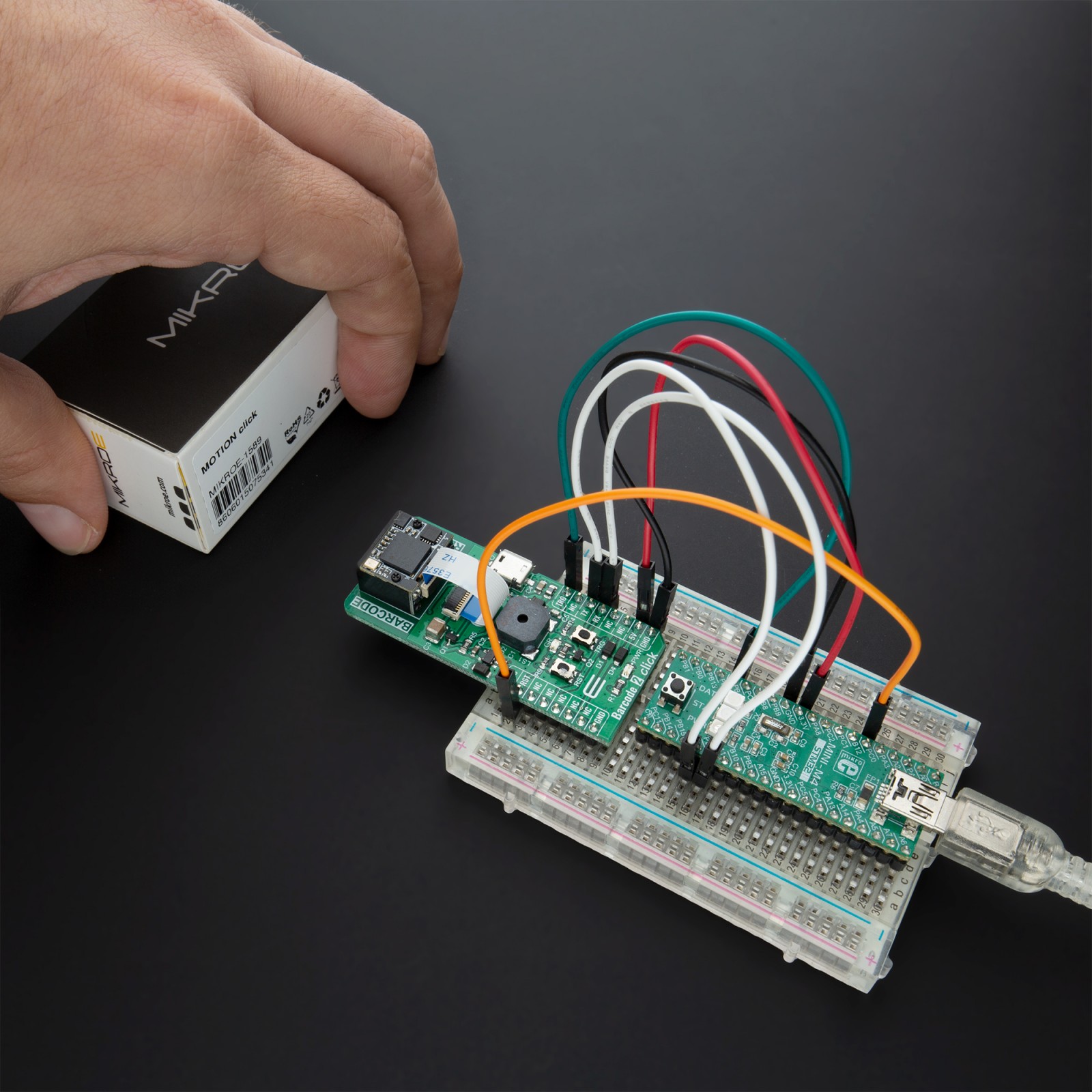
This Click board™ is designed to be operated only with a 5V logic voltage level. A proper logic voltage level conversion should be performed before the Click board™ is used with MCUs with different logic levels. However, the Click board™ comes equipped with a library that contains easy to use functions and an example code that can be used as a reference for further development.
Specifications
Type
Miscellaneous
Applications
Can be used for a for both emerging mobile phone-based barcode applications, like coupons, e-tickets and boarding passes, and traditional applications.
On-board modules
Barcode 2 Click is based on the EM3080-W, a barcode decoder chip that delivers superior performance and solid reliability with low power consumption from Newland Auto-ID Tech.
Key Features
Low power consumption, high reliability, quickly scan, excellent near-field reading, wide-viewing angle, and more.
Interface
UART,USB
Feature
No ClickID
Compatibility
mikroBUS™
Click board size
L (57.15 x 25.4 mm)
Input Voltage
5V
Pinout diagram
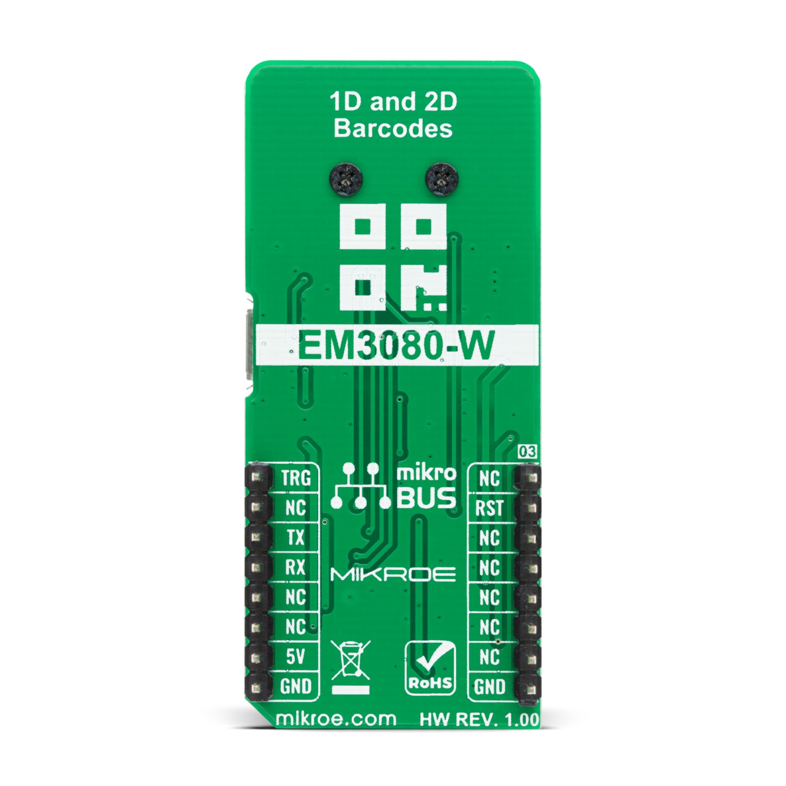
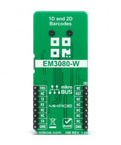
This table shows how the pinout on Barcode 2 Click corresponds to the pinout on the mikroBUS™ socket (the latter shown in the two middle columns).
Onboard settings and indicators
Label | Name | Default | Description |
---|---|---|---|
LD1 | PWR | – | Power LED Indicator |
LD2 | GR | – | Barcode Detection LED Indicator |
RST | Reset | – | Reset Button |
TRG | Trigger | – | Scanning Trigger Button |
LS1 | BUZZER | – | Magnetic Buzzer Transducer |
Barcode 2 Click electrical specifications
Description | Min | Typ | Max | Unit |
---|---|---|---|---|
Supply Voltage | -0.3 | – | +6 | V |
Scan Angle (Pitch & Skew) | – | ±45 | – | deg |
Power Consumption | – | 180.8 | – | mW |
Operating Temperature Range | -20 | – | +50 | °C |
Software Support
We provide a library for the Barcode 2 Click on our LibStock page, as well as a demo application (example), developed using MikroElektronika compilers. The demo can run on all the main MikroElektronika development boards.
Library Description
The library covers all the necessary functions to control Barcode 2 Click board. A library performs the communication with the device via UART interface.
Key functions:
uint8_t barcode2_read_byte( )
– Read Single Byte.void barcode2_enable_scaning ( uint8_t en_state )
– Enable scaning function.void barcode2_enable_reset ( uint8_t en_state )
– Enable reset function.
Examples description
The application is composed of three sections :
- System Initialization – Initializes UART used for communication and another UART bus used for data logging.
- Application Initialization – Initializes UART driver.
- Application Task – (code snippet) – This is an example that demonstrates the use of the Barcode 2 Click board. Barcode 2 Click starts scanning every 2 seconds. When the barcode is detected, program enters interrupt routine and displays a scanned barcode or QRcode data. Then disables scanning also in an interval of 2 seconds. Results are being sent to the Usart Terminal where you can track their changes.
void application_task ( ) { mikrobus_logWrite( "---------------------", _LOG_LINE ); mikrobus_logWrite( " Scan barcodes: ", _LOG_LINE ); barcode2_enable_scaning( BARCODE2_ENABLE ); Delay_ms( 2000 ); mikrobus_logWrite( "", _LOG_LINE ); mikrobus_logWrite( "---------------------", _LOG_LINE ); mikrobus_logWrite( " Scanning is off ", _LOG_LINE ); barcode2_enable_scaning( BARCODE2_DISABLE ); Delay_ms( 2000 ); }
The full application code, and ready to use projects can be found on our LibStock page.
Other mikroE Libraries used in the example:
- UART
- Conversions
Additional notes and informations
Depending on the development board you are using, you may need USB UART click, USB UART 2 click or RS232 click to connect to your PC, for development systems with no UART to USB interface available on the board. The terminal available in all MikroElektronika compilers, or any other terminal application of your choice, can be used to read the message.
mikroSDK
This Click board™ is supported with mikroSDK – MikroElektronika Software Development Kit. To ensure proper operation of mikroSDK compliant Click board™ demo applications, mikroSDK should be downloaded from the LibStock and installed for the compiler you are using.
For more information about mikroSDK, visit the official page.