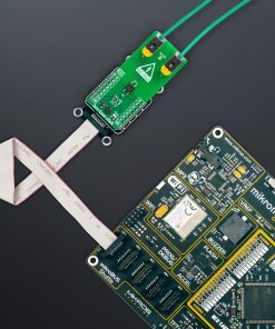
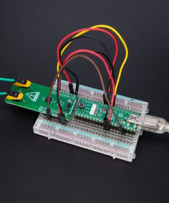
How does it work?
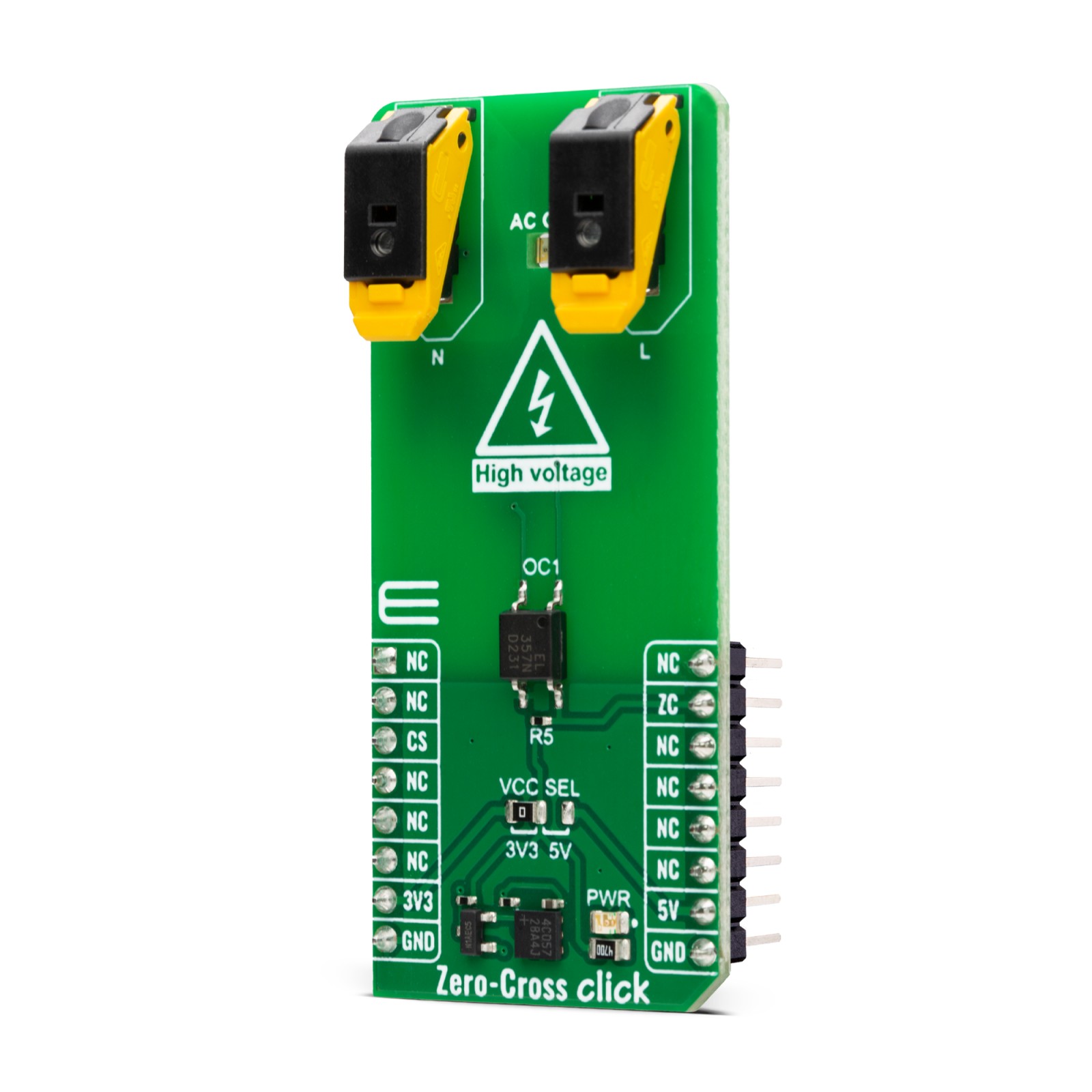
Zero-Cross Click is based on the circuitry that provides Zero Crossing Detection (ZCD). The alternate current can be connected over two block terminals. As it is intended for this Click board™ to work with high voltages, the critical components are placed on the bottom side, but still, take all precautions when working with this Click board™. On the top side is an AC ON LED for visual presentation of the AC presence. All the magic is happening in the circuitry at the bottom side of this Click board™.
The current passes through the Graetz bridge circuitry, consisting of four DLGL5980. The alternate current converts to a direct current, which is necessary for driving an LED in an EL357N-G, a phototransistor photocoupler from Everlight. When activated, the optocoupler sends a LOW logic state to a ZC pin, which is the pin with which the Zero-Cross Click communicates with the host MCU.
This Click board™ can operate with either 3.3V or 5V logic voltage levels selected via the VCC SEL jumper. This way, both 3.3V and 5V capable MCUs can use the communication lines properly. Also, this Click board™ comes equipped with a library containing easy-to-use functions and an example code that can be used, as a reference, for further development.
Specifications
Type
Optocoupler
Applications
Can be used for the development of frequency counters, phase meters, time-maker generators, and more
On-board modules
The circuitry that provides Zero Crossing Detection (ZCD)
Key Features
Pulse wave generator circuit, alternate current presence, zero crossing detection from positive to negative, and from negative to positive, block terminals for connecting high voltages, and more
Interface
GPIO
Feature
ClickID
Compatibility
mikroBUS™
Click board size
L (57.15 x 25.4 mm)
Input Voltage
3.3V or 5V,External
Pinout diagram
This table shows how the pinout on Zero-Cross Click corresponds to the pinout on the mikroBUS™ socket (the latter shown in the two middle columns).
Onboard settings and indicators
Label | Name | Default | Description |
---|---|---|---|
LD1 | PWR | – | Power LED Indicator |
LD2 | AC ON | – | AC Voltage Presence LED Indicator |
JP1 | VCC SEL | Left | Logic Level Voltage Selection 3V3/5V: Left position 3V3, Right position 5V |
Zero-Cross Click electrical specifications
Description | Min | Typ | Max | Unit |
---|---|---|---|---|
Supply Voltage | 3.3 | – | 5 | V |
AC Voltage Range | – | 220 | – | V |
Software Support
We provide a library for the Zero-Cross Click as well as a demo application (example), developed using MIKROE compilers. The demo can run on all the main MIKROE development boards.
Package can be downloaded/installed directly from NECTO Studio Package Manager (recommended), downloaded from our LibStock™ or found on Mikroe github account.
Library Description
This library contains API for Zero-Cross Click driver.
Key functions
-
zerocross_pin_read
Zero-Cross pin reading function. -
zerocross_get_freq
Zero-Cross frequency reading function.
Example Description
This example demonstrates the use of the Zero-Cross Click board™.
void application_task ( void )
{
float freq_val = 0;
zerocross_get_freq( &zerocross, &freq_val );
log_printf( &logger, " Freq %.2f Hz nr", freq_val );
}
The full application code, and ready to use projects can be installed directly from NECTO Studio Package Manager (recommended), downloaded from our LibStock™ or found on Mikroe github account.
Other Mikroe Libraries used in the example:
- MikroSDK.Board
- MikroSDK.Log
- Click.ZeroCross
Additional notes and informations
Depending on the development board you are using, you may need USB UART click, USB UART 2 Click or RS232 Click to connect to your PC, for development systems with no UART to USB interface available on the board. UART terminal is available in all MIKROE compilers.
mikroSDK
This Click board™ is supported with mikroSDK – MIKROE Software Development Kit. To ensure proper operation of mikroSDK compliant Click board™ demo applications, mikroSDK should be downloaded from the LibStock and installed for the compiler you are using.
For more information about mikroSDK, visit the official page.