XPort EDGE Click
R2,650.00 ex. VAT
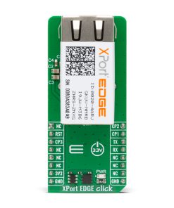
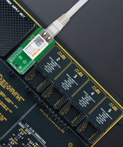
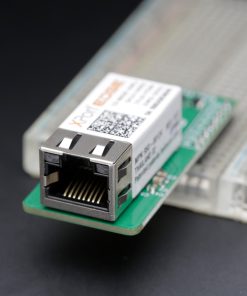
XPort EDGE Click is a compact add-on board for secure wired Ethernet connectivity for embedded applications, enabling device-to-cloud communication and remote management capabilities. It is based on the XPE200100S module from Lantronix, a next-generation embedded Ethernet gateway integrated with the Percepxion™ IoT edge solution. This board features an integrated RJ45 connector with magnetics, supports 10/100 Mbps Ethernet via IEEE 802.3-compliant MAC/PHY, and offers built-in support for advanced networking protocols and Lantronix’s TruPort® Serial and TruPort® Socket technologies for flexible serial-to-Ethernet bridging. With 8MB flash memory for firmware and web content, plus robust Infinishield™ Security, this Click ensures high-integrity data transmission and device safety for industrial automation, remote equipment monitoring, smart infrastructure, and any embedded system requiring secure and manageable Ethernet-based network access.
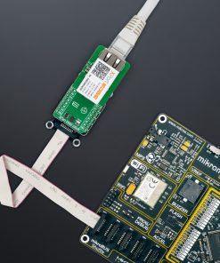
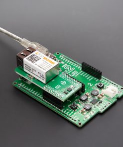
XPort EDGE Click is fully compatible with the mikroBUS™ socket and can be used on any host system supporting the mikroBUS™ standard. It comes with the mikroSDK open-source libraries, offering unparalleled flexibility for evaluation and customization. What sets this Click board™ apart is the groundbreaking ClickID feature, enabling your host system to automatically detect and identify this add-on board.
Stock: Lead-time applicable.
| 5+ | R2,517.50 |
| 10+ | R2,385.00 |
| 15+ | R2,252.50 |
| 20+ | R2,167.70 |
How does it work?
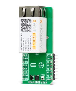
XPort EDGE Click is based on the XPE200100S module from Lantronix, offering a next-generation wired Ethernet gateway and embedded device server in the same compact form factor as the original XPort series. This board is designed to enable secure, reliable, and manageable Ethernet connectivity for industrial and IoT applications by integrating the capabilities of the XPort EDGE platform along with the Percepxion™ cloud-based IoT edge solution. The integrated RJ45 jack includes magnetics and supports 10/100 Mbps Ethernet through an IEEE 802.3-compliant MAC and PHY with HP Auto-MDIX and auto-negotiation for full or half-duplex operation, all within a standard Ethernet connector.

The module supports advanced network protocols including IPv4/IPv6, TCP/IP, UDP/IP, DHCP, BOOTP, ARP, ICMP, Auto-IP, DNS, SNMP v1/v2, Telnet, and HTTP, making it suitable for diverse networking scenarios. With built-in support for Lantronix’s customer-proven TruPort® Serial and TruPort® Socket technologies, the XPort EDGE Click ensures secure data communication through transparent pass-through of serial protocols or multi-session TCP, UDP, and HTTP(S) connections. It supports a maximum serial data rate of 4 Mbps, configurable via software, and it is pre-integrated with the Percepxion™ software platform for remote management, real-time monitoring, and application integration, streamlining deployment in both cloud-connected and on-premise environments.
A standout feature is the robust security framework powered by Lantronix’s Infinishield™ Security, which includes secure boot, secure firmware updates (FOTA), secure network attachment via EAPOL, role-based access control, data-at-rest protection for encryption keys and configurations, and fine-grained policy control over network services. These built-in protections minimize the need for additional integration effort while ensuring compliance with modern cybersecurity standards. With its industrial-grade reliability, advanced networking capabilities, and comprehensive device-level security, XPort EDGE Click delivers a complete Ethernet connectivity and device management solution for modern embedded applications.
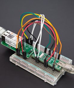
Communication with the host device is achieved via UART interface and three configurable general-purpose I/O pins (CP1, CP2, and CP3), which can function as flow/modem control lines or general-purpose signals. In addition, the XPort includes 8MB of flash memory for storing firmware and web content, enabling full customization and remote management of connected devices. As mentioned, the module connects directly to an Ethernet network through the RJ45 port. Two bi-color LEDs integrated into the front of the connector provide real-time status indication.
This Click board™ can be operated only with a 3.3V logic voltage level. The board must perform appropriate logic voltage level conversion before using MCUs with different logic levels. It also comes equipped with a library containing functions and example code that can be used as a reference for further development.
Specifications
Type
Ethernet
Applications
Ideal for industrial automation, remote equipment monitoring, smart infrastructure, and any embedded system requiring secure and manageable Ethernet-based network access
On-board modules
XPE200100S – next-generation embedded Ethernet gateway integrated with the Percepxion™ IoT edge module from Lantronix
Key Features
Support for 10/100 Mbps Ethernet through IEEE 802.3-compliant MAC and PHY with HP Auto-MDIX, UART interface, TruPort Serial and TruPort Socket technologies, support for IPv4/IPv6, TCP/IP, UDP/IP, DHCP, BOOTP, ARP, ICMP, Auto-IP, DNS, SNMP v1/v2, Telnet, and HTTP protocols, 8MB of onboard flash memory, pre-integration with the Percepxion cloud-based IoT platform, built-in Infinishield Security, and more
Interface
UART
Feature
ClickID
Compatibility
mikroBUS™
Click board size
L (57.15 x 25.4 mm)
Input Voltage
3.3V
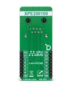
Pinout diagram
This table shows how the pinout on XPort EDGE Click corresponds to the pinout on the mikroBUS™ socket (the latter shown in the two middle columns).
| Notes | Pin | Pin | Notes | ||||
|---|---|---|---|---|---|---|---|
| NC | 1 | AN | PWM | 16 | CP2 | General-Purpose I/O | |
| ID SEL | RST | 2 | RST | INT | 15 | CP1 | General-Purpose I/O |
| General-Purpose I/O / ID COMM | CP3 | 3 | CS | RX | 14 | TX | UART TX |
| NC | 4 | SCK | TX | 13 | RX | UART RX | |
| NC | 5 | MISO | SCL | 12 | NC | ||
| NC | 6 | MOSI | SDA | 11 | NC | ||
| Power Supply | 3.3V | 7 | 3.3V | 5V | 10 | NC | |
| Ground | GND | 8 | GND | GND | 9 | GND | Ground |
Onboard settings and indicators
| Label | Name | Default | Description |
|---|---|---|---|
| LD1 | PWR | – | Power LED Indicator |
XPort EDGE Click electrical specifications
| Description | Min | Typ | Max | Unit |
|---|---|---|---|---|
| Supply Voltage | – | 3.3 | – | V |
| Ethernet Speed | 10 | – | 100 | Mbps |
Software Support
XPort EDGE Click demo application is developed using the NECTO Studio, ensuring compatibility with mikroSDK‘s open-source libraries and tools. Designed for plug-and-play implementation and testing, the demo is fully compatible with all development, starter, and mikromedia boards featuring a mikroBUS™ socket.
Example Description
This example demonstrates the functionality of the XPort EDGE Click board. It initializes the module, retrieves the device and interface information, performs diagnostic commands such as pinging a specific address, and allows the user to access the device via its web interface. Additionally, it provides a CLI (Command Line Interface) mode to UART terminal for further interaction with the device.
Key Functions
xportedge_cfg_setupThis function initializes Click configuration structure to initial values.xportedge_initThis function initializes all necessary pins and peripherals used for this Click board.xportedge_reset_deviceThis function resets device by toggling the RST pin state.xportedge_send_cmdThis function sends a command string by using UART serial interface.xportedge_list_commandsThis function lists commands at current level by sending the question mark by using UART serial interface.
Application Init
Initializes the logger and the XPort EDGE Click driver, performs a device reset, retrieves device information, and pings the specific address in diagnostics. The application retrieves the device’s IP address, enabling the user to connect via a web browser and access the web interface. Finally, it enters CLI mode for advanced command interactions.
Application Task
Continuously monitors UART communication, relaying commands and responses between the XPort EDGE Click board and the logger. This allows real-time interaction with the device through the UART Terminal for configuration and diagnostics.
Application Output
This Click board can be interfaced and monitored in two ways:
- Application Output – Use the “Application Output” window in Debug mode for real-time data monitoring. Set it up properly by following this tutorial.
- UART Terminal – Monitor data via the UART Terminal using a USB to UART converter. For detailed instructions, check out this tutorial.
Additional Notes and Information
The complete application code and a ready-to-use project are available through the NECTO Studio Package Manager for direct installation in the NECTO Studio. The application code can also be found on the MIKROE GitHub account.
Resources
Downloads
| Weight | 27 g |
|---|---|
| Brand | MikroElektronika |