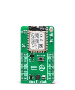

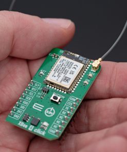
XBee 4 Click
R1,250.00 ex. VAT
XBee 4 Click is a compact add-on board for reliable wireless communication in industrial and commercial applications. This board features the XBRR-24Z8, a Zigbee 3.0 module from DIGI International, featuring a Silicon Labs EFR32MG transceiver chipset for efficient data transmission. Operating at 2.4GHz, it supports Zigbee Mesh networking, Bluetooth® Low Energy (BLE) 4.2, and offers a maximum RF data rate of 250Kbps with a serial speed of up to 1Mbps. It ensures strong and stable connectivity with an indoor range of up to 60m and an outdoor line-of-sight range of 1200m. The board communicates with the host MCU via UART or SPI interfaces, includes hardware flow control, and features LED indicators for status monitoring and a button for commissioning. XBee 4 Click is ideal for building automation, smart energy management, industrial monitoring, and intelligent lighting systems.
XBee 4 Click is fully compatible with the mikroBUS™ socket and can be used on any host system supporting the mikroBUS™ standard. It comes with the mikroSDK open-source libraries, offering unparalleled flexibility for evaluation and customization. What sets this Click board™ apart is the groundbreaking ClickID feature, enabling your host system to seamlessly and automatically detect and identify this add-on board.
Stock: Lead-time applicable.
| 5+ | R1,187.50 |
| 10+ | R1,125.00 |
| 15+ | R1,062.50 |
| 20+ | R1,022.50 |
How does it work?
XBee 4 Click is based on the XBRR-24Z8, a powerful Zigbee 3.0 module from DIGI International designed for wireless communication in various industrial and commercial applications. Operating within the 2.4GHz frequency range, this module integrates a Silicon Labs EFR32MG transceiver chipset, ensuring reliable data transmission. With a maximum RF data rate of 250Kbps and a serial communication speed of up to 1Mbps, it enables wireless connectivity across a wide range of smart applications. It supports Zigbee Mesh networking, providing connectivity for applications such as building automation, smart energy management, digital health solutions, and intelligent lighting systems.

One of the key advantages of this module is its impressive communication range. Under optimal conditions with minimal interference, the indoor and urban range extends to 60 meters (200 feet), while the outdoor line-of-sight range reaches up to 1200 meters (4000 feet). Additionally, the module operates with a transmit power of +8dBm and a receiver sensitivity of -103dBm in normal mode, ensuring strong and stable signal reception even in challenging environments. Alongside Zigbee connectivity, it also supports Bluetooth® Low Energy (BLE) 4.2, allowing interoperability with BLE 5.0 devices that support the 1M PHY mode. In BLE operation, the indoor range extends up to 15 meters (49 feet), while the outdoor line-of-sight range reaches 300 meters (984 feet), with a transmission power of +8dBm and a receiver sensitivity of -95dBm.
The module has a 1MB flash memory and 96kB of RAM, providing ample storage for firmware and application data. Its compatibility with Zigbee 3.0 ensures full interoperability with a broad ecosystem of Zigbee-certified devices, making it an ideal solution for large-scale wireless networks. The module has received regulatory approvals in North America and Europe, allowing seamless deployment in multiple regions without additional certification requirements.
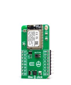
This Click board™ achieves communication between the XBRR-24Z8 module and the host MCU through a UART interface, standard UART RX and TX pins, and hardware flow control via CTS and RTS pins. Additionally, it supports SPI communication (peripheral-only). The RTS pin is multiplexed with the SPI Chip Select (CS) pin on the SEL pin, allowing the selection of its function via the COM pin – set to 1 for RTS functionality or 0 for CS. By default, the UART communication speed is configured at 115200bps. Besides the interface pins, the board also uses a Sleep (SLP) pin (active high) for managing the module’s low-power mode and a Reset (RST) pin (active low), allowing users to reset the module whenever necessary.
This Click board™ also includes several LED indicators to provide real-time status feedback. The red ATT LED is an SPI attention indicator, signaling when the module requires SPI communication with the host MCU. The green ON LED serves as a device status indicator, confirming the operational state of the module. Additionally, the yellow ASC LED acts as an Associate indicator, working with the onboard commissioning button to simplify the deployment and integration of new Zigbee devices into an existing Zigbee network. The commissioning process enables network inclusion by configuring the device to communicate with other nodes, ensuring a stable and functional Zigbee mesh network.
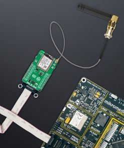
The board features one u.Fl connector for Sub-GHz antennas that MIKROE offers, like the 868MHz Straight Rubber Antenna, combined with an IPEX-SMA cable for flexible and efficient connectivity options.
This Click board™ can be operated only with a 3.3V logic voltage level. The board must perform appropriate logic voltage level conversion before using MCUs with different logic levels. It also comes equipped with a library containing functions and example code that can be used as a reference for further development.
Specifications
Type
ZigBee
Applications
Ideal for building automation, smart energy management, industrial monitoring, and intelligent lighting system
On-board modules
XBRR-24Z8 – Zigbee 3.0 module from DIGI International
Key Features
Zigbee 3.0 and Bluetooth® Low Energy (BLE) 4.2 support, Silicon Labs EFR32MG transceiver chipset, 2.4GHz frequency operation, RF data rates up to 250Kbps, UART and SPI interfaces, Commissioning button for seamless Zigbee device integration, LED indicators, and more
Interface
SPI,UART
Feature
ClickID
Compatibility
mikroBUS™
Click board size
M (42.9 x 25.4 mm)
Input Voltage
3.3V
Pinout diagram
This table shows how the pinout on XBee 4 Click corresponds to the pinout on the mikroBUS™ socket (the latter shown in the two middle columns).
| Notes | Pin | Pin | Notes | ||||
|---|---|---|---|---|---|---|---|
| Sleep Mode Control | SLP | 1 | AN | PWM | 16 | COM | RTS/CS Selection |
| Reset / ID SEL | RST | 2 | RST | INT | 15 | CTS | UART CTS |
| UART RTS / SPI Select / ID COMM | SEL | 3 | CS | RX | 14 | TX | UART TX |
| SPI Clock | SCK | 4 | SCK | TX | 13 | RX | UART RX |
| SPI Data OUT | SDO | 5 | MISO | SCL | 12 | NC | |
| SPI Data IN | SDI | 6 | MOSI | SDA | 11 | NC | |
| Power Supply | 3.3V | 7 | 3.3V | 5V | 10 | NC | |
| Ground | GND | 8 | GND | GND | 9 | GND | Ground |
Onboard settings and indicators
| Label | Name | Default | Description |
|---|---|---|---|
| LD1 | PWR | – | Power LED Indicator |
| LD2 | ASC | – | Associate LED Indicator |
| LD3 | ON | – | Device Status LED Indicator |
| LD4 | ATT | – | SPI Attention LED Indicator |
| T1 | BUTTON | – | Commissioning Button |
XBee 4 Click electrical specifications
| Description | Min | Typ | Max | Unit |
|---|---|---|---|---|
| Supply Voltage | – | 3.3 | – | V |
| Frequency | – | 2.4 | – | GHz |
| Data Rate | – | – | 250 | Kbps |
| TX Power | – | +8 | – | dBm |
| RX Sensitivity | – | -103 | – | dBm |
Software Support
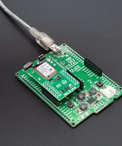
XBee 4 Click demo application is developed using the NECTO Studio, ensuring compatibility with mikroSDK‘s open-source libraries and tools. Designed for plug-and-play implementation and testing, the demo is fully compatible with all development, starter, and mikromedia boards featuring a mikroBUS™ socket.
Example Description
This example demonstrates the use of an XBee 4 Click by showing the communication between the two Click boards configured in transparent mode.
Key Functions
xbee4_cfg_setupConfig Object Initialization function.xbee4_initInitialization function.xbee4_get_serial_numberThis function sends a get serial number command.xbee4_set_device_nameThis function sets the device name (node identifier).xbee4_set_destination_addressThis function sets the destination address high and low bytes.
Application Init
Initializes the driver and configures the Click board by performing a factory reset, and setting the device name, destination address, api mode to transparent, and a device role to join or form network depending on the application mode.
Application Task
Depending on the selected application mode, it reads all the received data or sends the desired message every 3 seconds.
Application Output
This Click board can be interfaced and monitored in two ways:
- Application Output – Use the “Application Output” window in Debug mode for real-time data monitoring. Set it up properly by following this tutorial.
- UART Terminal – Monitor data via the UART Terminal using a USB to UART converter. For detailed instructions, check out this tutorial.
Additional Notes and Information
The complete application code and a ready-to-use project are available through the NECTO Studio Package Manager for direct installation in the NECTO Studio. The application code can also be found on the MIKROE GitHub account.
Resources
Downloads
| Weight | 18 g |
|---|---|
| Brand | MikroElektronika |