How does it work?
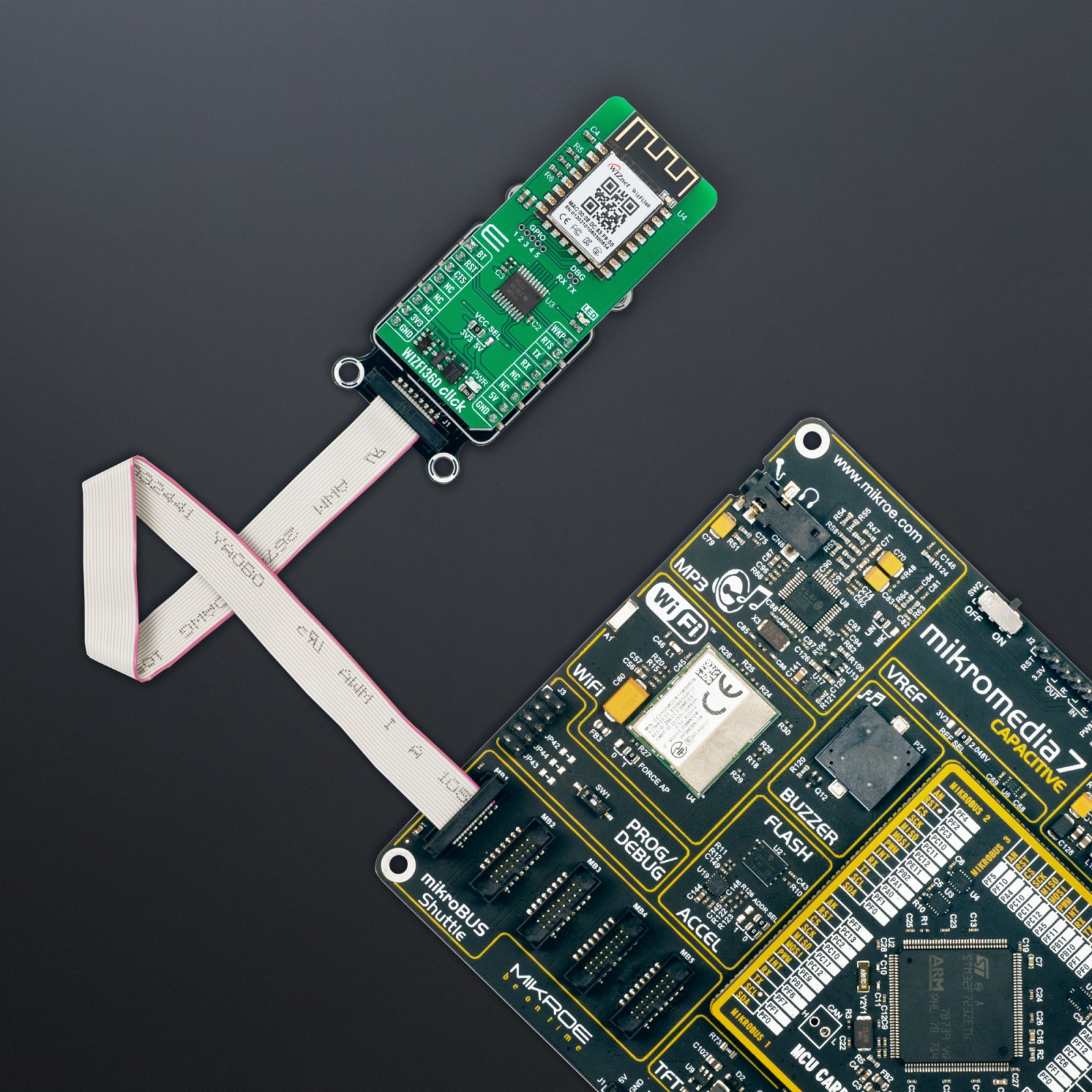
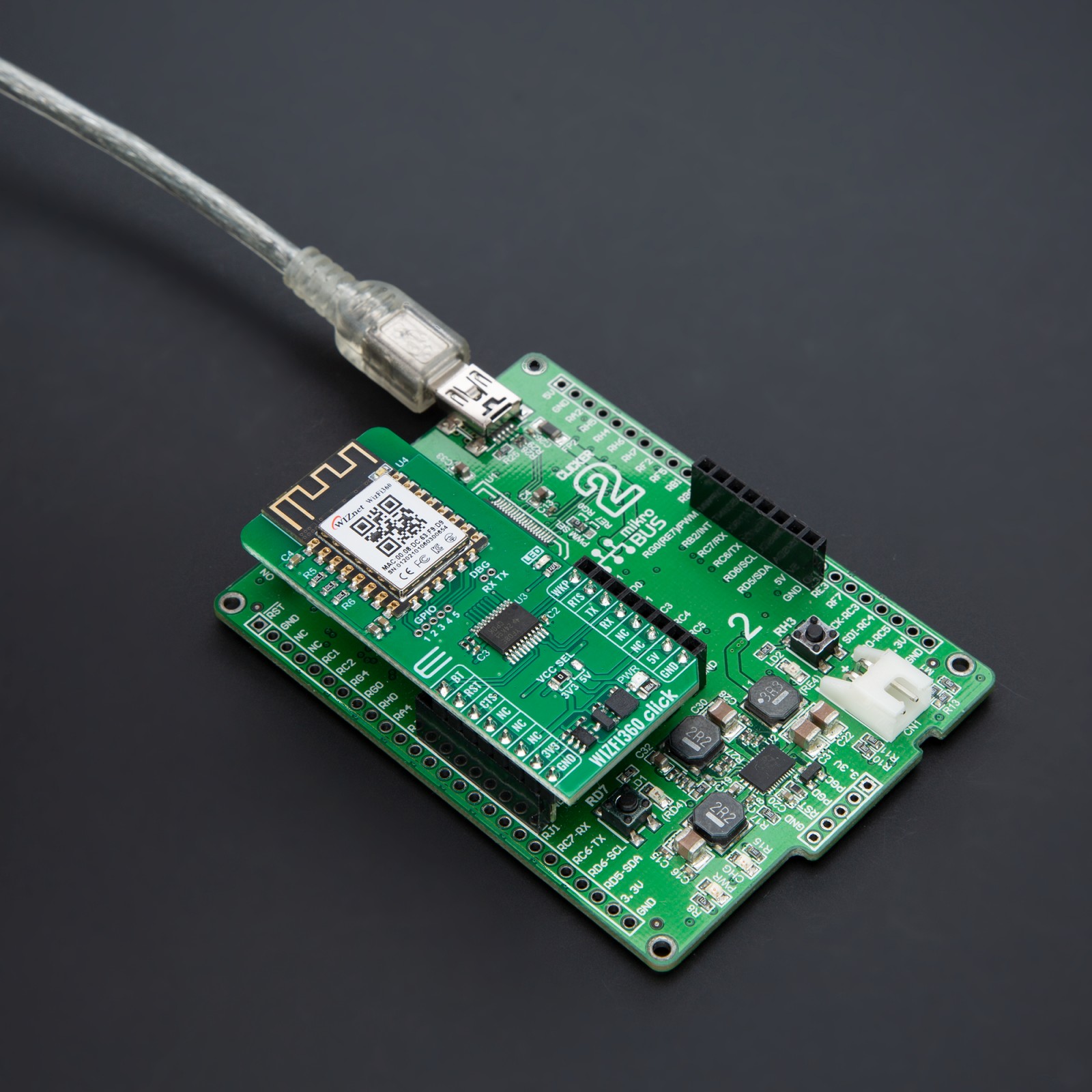
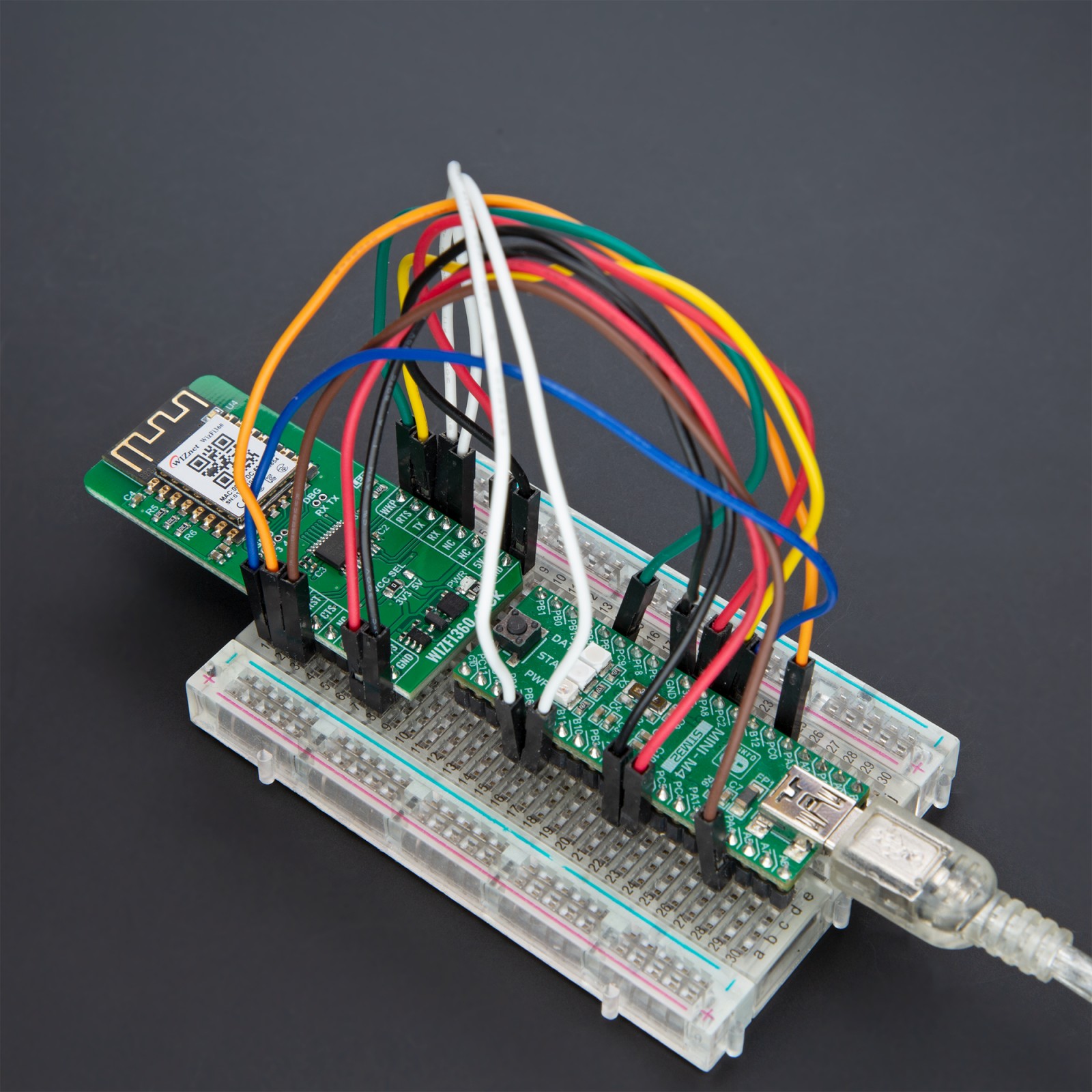
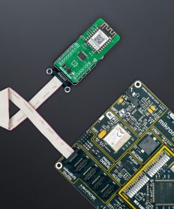
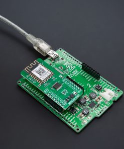
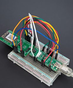
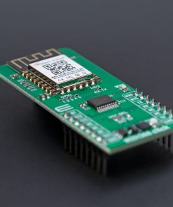
WIZFI360 Click is based on the WIZFI360, an advanced and cost-effective WiFi module from WIZnet designed for industrial-grade applications. The WIZFI360 features low power consumption and full compliance with the IEEE802.11 b/g/n standard. This allows the module to support WiFi 2.4G with SoftAP, Station, and SoftAP+Station modes, operating within the frequency range of 2400MHz to 2483.5MHz. Thanks to the WIZFI360, this Click board™ offers a versatile serial port baud rate of up to 2Mbps, catering to various application requirements like reliable WiFi connectivity in various industrial applications.
The WIZFI360 offers robust features designed to ensure versatility and reliability in wireless networks. One of its standout capabilities is supporting both “Data pass-through” and “AT command data transfer” modes, which provide flexible data communication options. The module’s serial AT command configuration capability further enhances its usability, allowing for easy setup and management. Additionally, it supports multiple operating modes, including TCP Server, TCP Client, and UDP, making it adaptable to various networking requirements. With configurable operating channels from 1 to 13 and automatic 20MHz/40MHz bandwidth support, the WIZFI360 Click ensures optimal performance and adaptability to different network environments.
Security and connectivity are also prioritized in the WIZFI360 Click’s design. It supports WPA_PSK and WPA2_PSK encryption, ensuring secure wireless communication. The module accommodates a wide range of serial port baud rates from 600bps to 2Mbps, with 16 common values, catering to diverse application needs. It can handle up to 5 simultaneous TCP/UDP links, providing robust connectivity options. For ease of network integration, it supports automatic IP address acquisition from the DHCP server in Station mode and offers DHCP services for Wireless LAN clients in AP mode. DNS support allows for server communication using domain names, while the “Keep-Alive” feature monitors TCP connections to maintain stability. Additionally, the “Ping” feature aids network status monitoring, and the built-in SNTP client ensures accurate synchronization of network time. The module also includes a unique built-in MAC address with user configurability, enhancing network security and management.
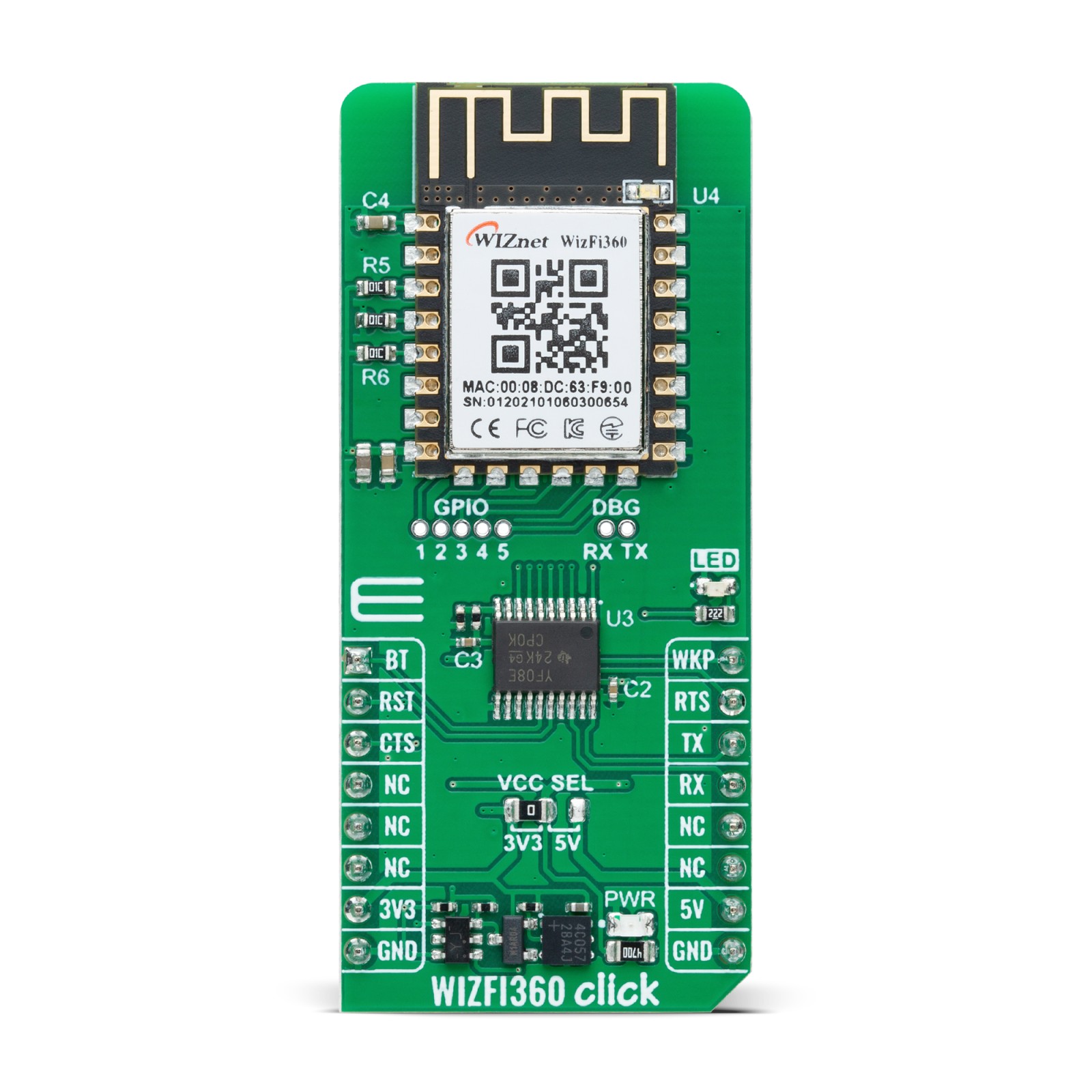
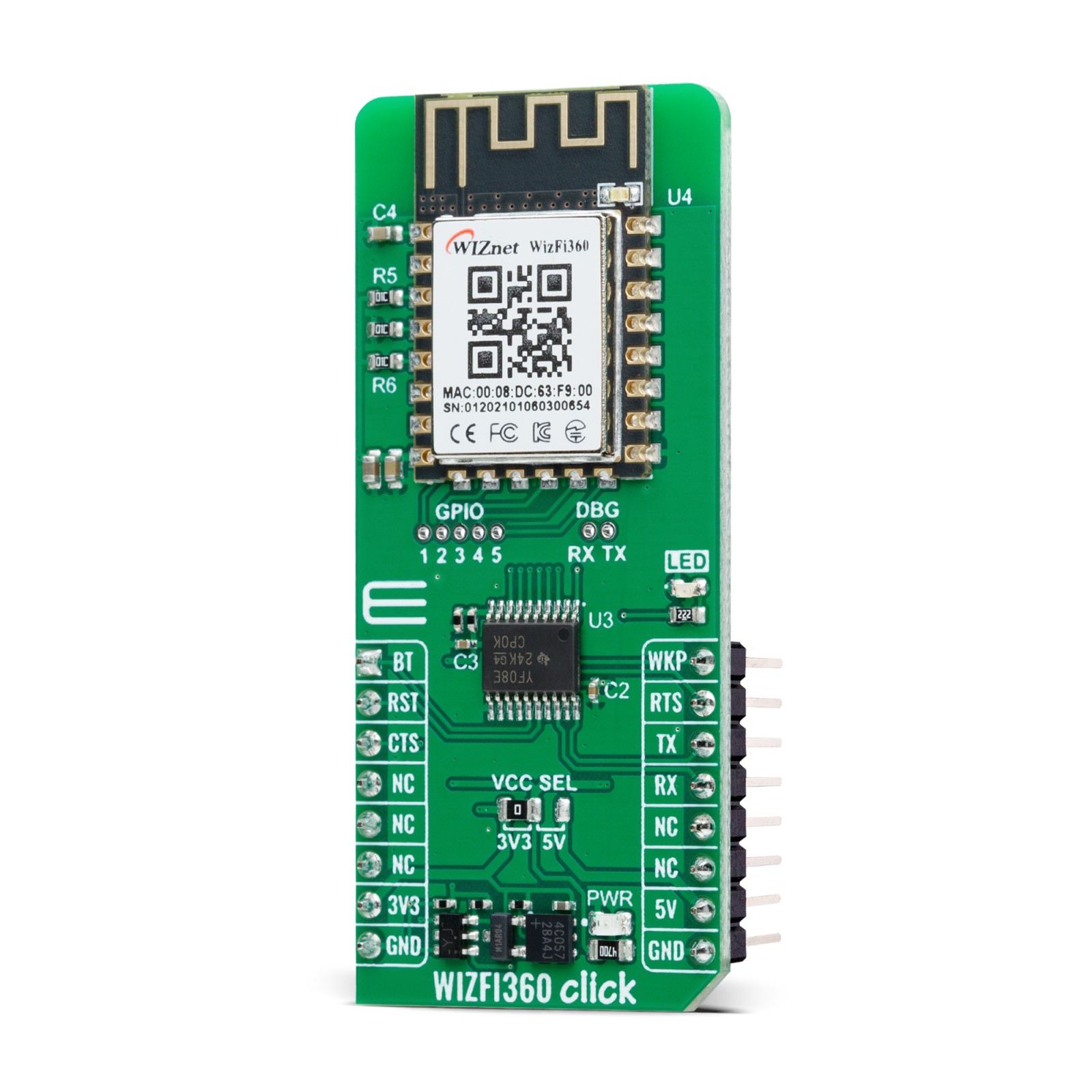
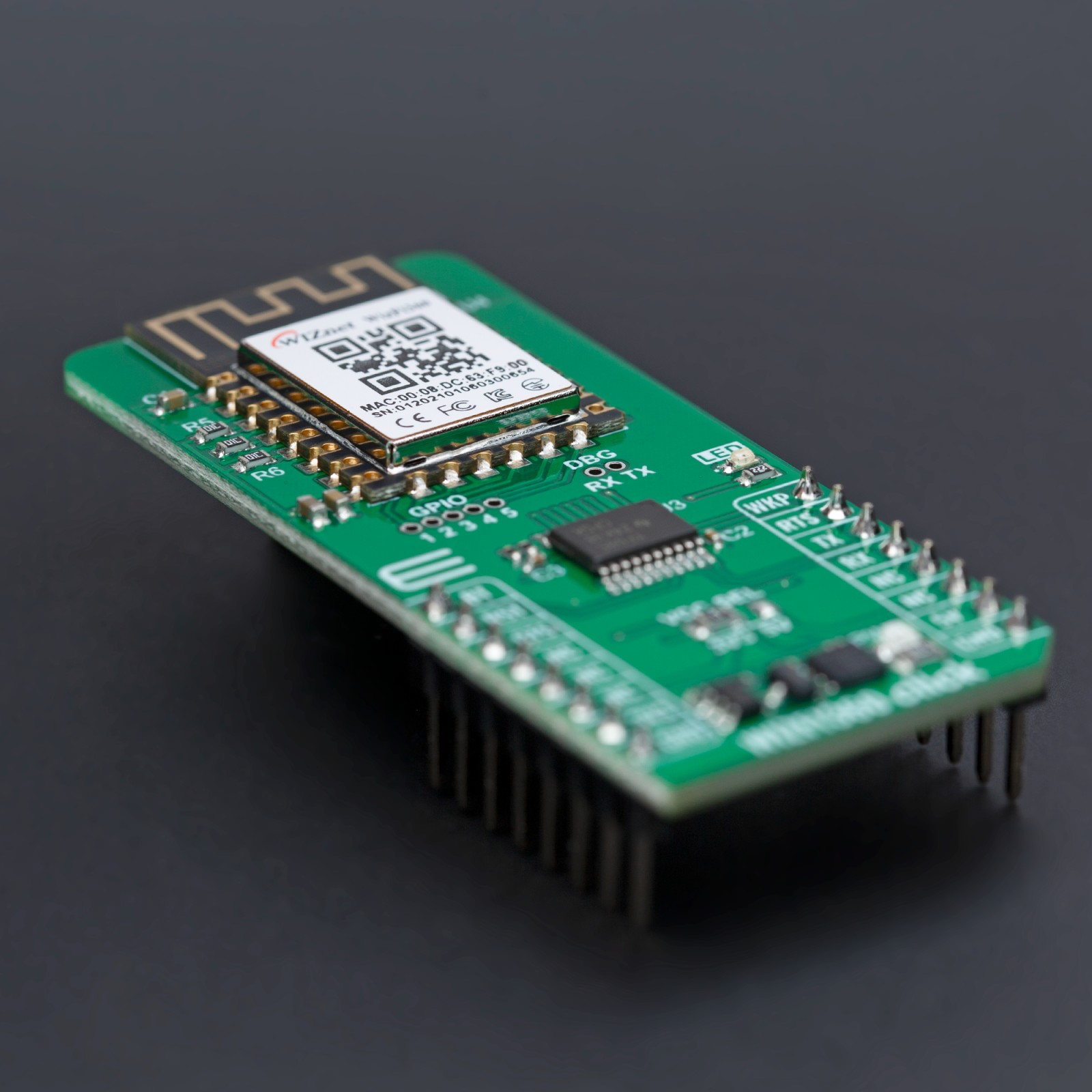
Communication between the WIZFI360 module and the host MCU is established through a UART interface, standard UART RX and TX pins, and hardware flow control pins (CTS/RTS). The default communication speed is 115200bps, ensuring efficient data exchange. The board also includes a reset (RST) pin for hard resetting the module, a wake-up WKP pin for waking the module from Sleep mode, and a Boot (BT) pin to trigger the bootloader mode for firmware updates when set to a low logic level during reset.
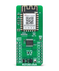
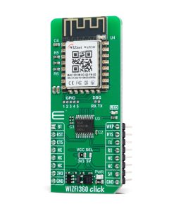
The WIZFI360 Click also features a red LED that indicates data transmission and reception activity, providing a clear visual cue for network communication status. In addition to this, the board also includes two unpopulated headers for added functionality. The first header, DBG, serves as a UART0 interface for debugging and firmware upgrades, allowing users to troubleshoot and update the module easily. The second header, labeled GPIO, offers several GPIO pins from the module (from IO1 to IO5), allowing users to utilize these pins for various custom applications and additional interfacing requirements.
This Click board™ can operate with both 3.3V and 5V logic voltage levels selected via the VCC SEL jumper. Given that the WIZFI360 module operates at 3.3V, a logic-level translator, TXS0108E, is also used for proper operation and an accurate signal-level translation. This way, both 3.3V and 5V capable MCUs can use the communication lines properly. Also, this Click board™ comes equipped with a library containing easy-to-use functions and an example code that can be used as a reference for further development.
Specifications
Type
WiFi
Applications
Ideal for industrial automation, smart metering, and remote monitoring systems
On-board modules
WIZFI360 – advanced WiFi module from WIZnet
Key Features
Robust and versatile 2.4GHz WiFi connectivity, SoftAP, Station, and SoftAP+Station modes, fully compliant with IEEE802.11 b/g/n standards, a serial port baud rate of up to 2Mbps, configurable operating channels from 1 to 13, automatic 20MHz/40MHz bandwidth support, WPA_PSK and WPA2_PSK encryption for secure communication, can manage up to 5 simultaneous TCP/UDP links, supports both “Data pass-through” and “AT command data transfer” modes, DNS support for server communication, and many more
Interface
UART
Feature
ClickID
Compatibility
mikroBUS™
Click board size
L (57.15 x 25.4 mm)
Input Voltage
3.3V or 5V
Pinout diagram
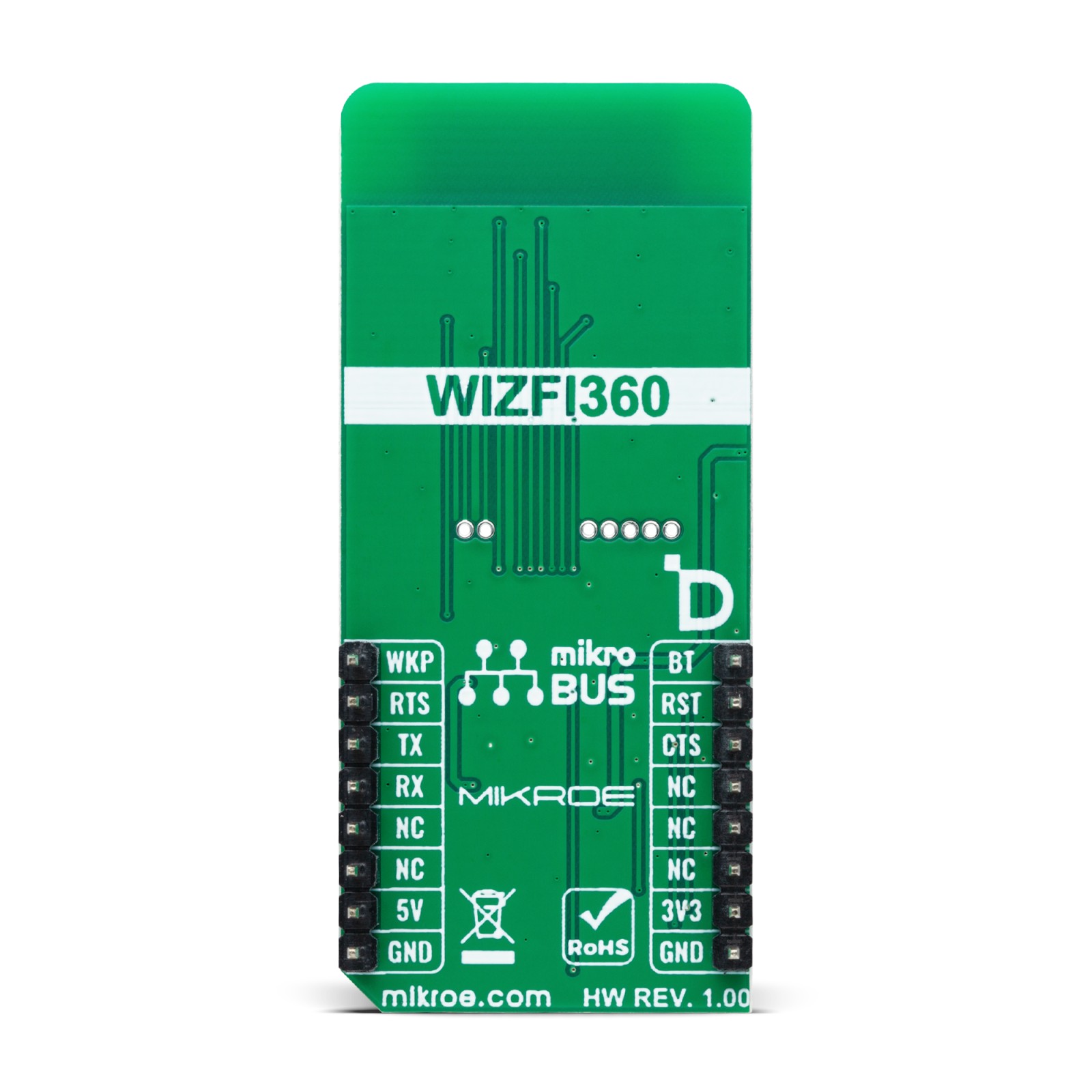
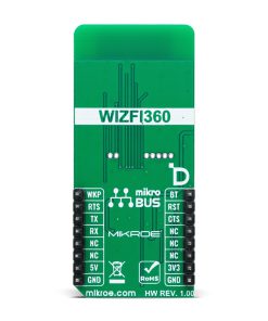
This table shows how the pinout on WIZFI360 Click corresponds to the pinout on the mikroBUS™ socket (the latter shown in the two middle columns).
Onboard settings and indicators
Label | Name | Default | Description |
---|---|---|---|
LD1 | PWR | – | Power LED Indicator |
LD2 | LED | – | TX/RX Packet LED Indicator |
JP1 | VCC SEL | Left | Power Voltage Level Selection 3V3/5V: Left position 3V3, Right position 5V |
WIZFI360 Click electrical specifications
Description | Min | Typ | Max | Unit |
---|---|---|---|---|
Supply Voltage | 3.3 | – | 5 | V |
Frequency Range | – | 2.4 | – | GHz |
Software Support
We provide a library for the WIZFI360 Click as well as a demo application (example), developed using MIKROE compilers. The demo can run on all the main MIKROE development boards.
Package can be downloaded/installed directly from NECTO Studio Package Manager (recommended), downloaded from our LibStock™ or found on MIKROE github account.
Library Description
This library contains API for WIZFI360 Click driver.
Key functions
-
wizfi360_write_command
This function writes a desired command by using the UART serial interface. -
wizfi360_write_cmd_param
This function writes a desired command, prefix and parameter by using UART serial interface. -
wizfi360_send_message
This function sends messages to the host in normal transmission mode using the UART serial interface.
Example Description
This example demonstrates the use of the WIZFI360 Click board™ by processing the incoming data and displaying them on the USB UART.
void application_task ( void )
{
wizfi360_inquire_command( &wizfi360, WIZFI360_CMD_CIPSNTPTIME );
wizfi360_check_response( WIZFI360_RSP_OK );
Delay_ms( 1000 );
wizfi360_write_cmd_param( &wizfi360, WIZFI360_CMD_CIPSEND,
WIZFI360_PREFIX_SYMB_SET_VAL,
DEMO_SEND_DATA_LENGTH );
wizfi360_check_response( WIZFI360_RSP_OK );
Delay_ms( 500 );
wizfi360_send_message( &wizfi360, DEMO_SEND_DATA );
wizfi360_check_response( WIZFI360_RSP_READY_FOR_SEND );
Delay_ms( 5000 );
}
The full application code, and ready to use projects can be installed directly from NECTO Studio Package Manager (recommended), downloaded from our LibStock™ or found on MIKROE github account.
Other MIKROE Libraries used in the example:
- MikroSDK.Board
- MikroSDK.Log
- Click.WIZFI360
Additional notes and informations
Depending on the development board you are using, you may need USB UART click, USB UART 2 Click or RS232 Click to connect to your PC, for development systems with no UART to USB interface available on the board. UART terminal is available in all MIKROE compilers.
mikroSDK
This Click board™ is supported with mikroSDK – MIKROE Software Development Kit. To ensure proper operation of mikroSDK compliant Click board™ demo applications, mikroSDK should be downloaded from the LibStock and installed for the compiler you are using.
For more information about mikroSDK, visit the official page.