How does it work?
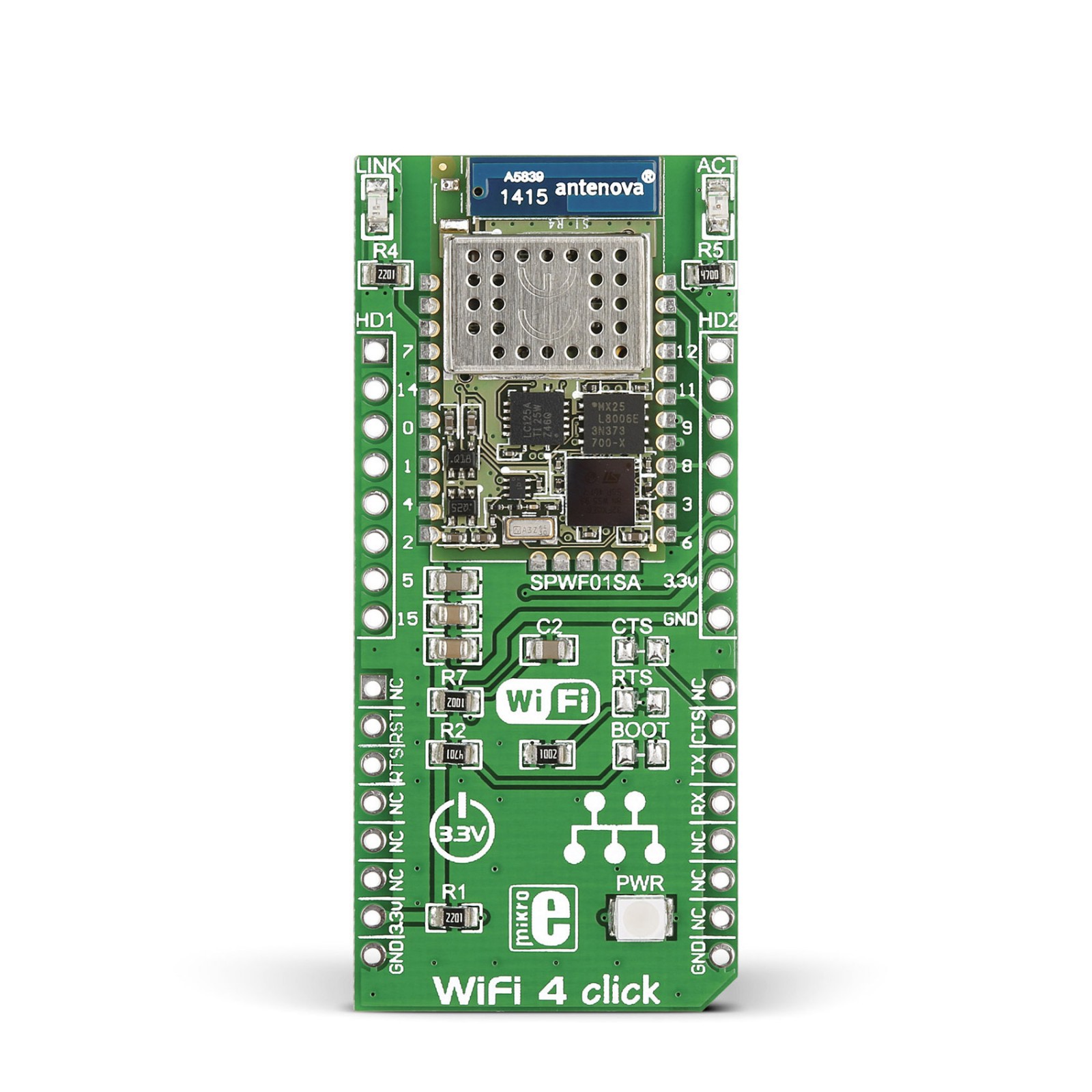
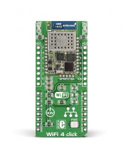
WiFi 4 Click is based on the SPWF01SA, a serial-to-WiFi b/g/n intelligent module from STMicroelectronics. The module includes the 2.4GHz IEEE802.11 b/g/n transceiver and STM32 ARM Cortex-M3 microcontroller with 64KB RAM and 512KB Flash memory. It also has a chip antenna to connect successfully to the 2400MHz frequency band and can achieve up to +18dBm of output power. The SPWF01SA module features advanced low-power modes, firmware updates via the UART interface, FOTA (over-the-air), and a simple AT command set. Depending on the modulation, this Click board™ can achieve 1Mbps with DSSS or even up to 54Mbps using OFDM.
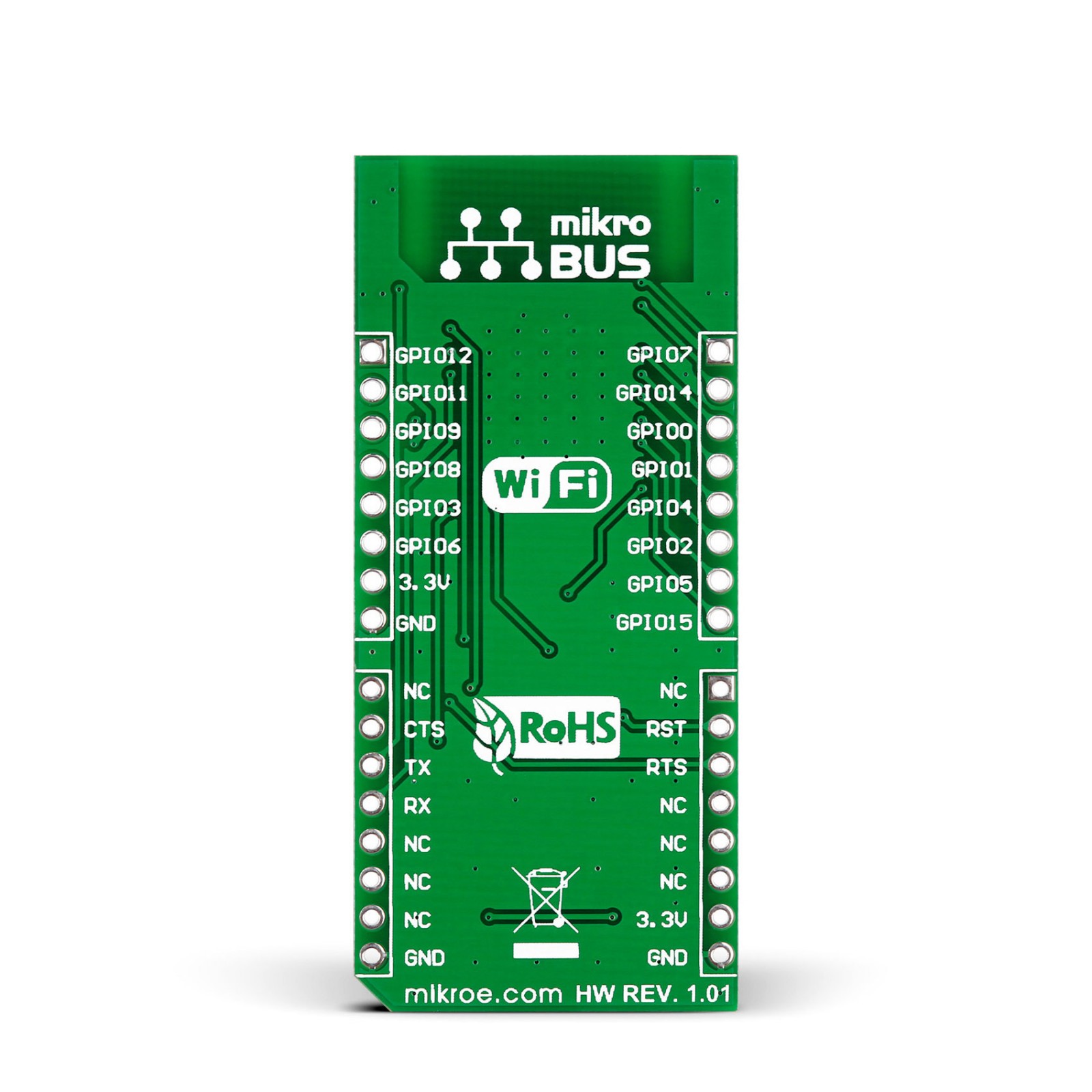
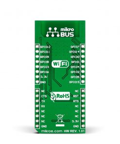
To communicate with the host MCU, the WiFi 4 Click uses the UART interface of the mikroBUS™ socket, with commonly used UART RX and TX pins. It also uses additional pins, such as the RST pin, that resets the WiFi module with a low logic state. The RTS and CTS pins go over unpopulated RTS and CTS solder jumpers to corresponding pins of the mikroBUS™ socket and can be used by the host MCU if shortening them. The unpopulated BOOT solder jumper can put the onboard STM32 MCU into bootloader mode. In addition, this Click board™ features HD1 and HD2 headers with SPWF01SA user-configurable GPIO pins. Besides its general-purpose functionality, pin 14 can also be used as a Power Up status pin for monitoring purposes. The module has a WiFi Link and Active LEDs to visually present module statuses.
This Click board™ can only be operated from a 3.3V logic voltage level. Therefore, the board must perform appropriate logic voltage conversion before using MCUs with different logic levels. However, the Click board™ comes equipped with a library containing functions and an example code that can be used as a reference for further development.
Specifications
Type
WiFi
Applications
Can be used for industrial wireless control, smart home applications, utility and smart energy, remote device management, and more
On-board modules
SPWF01SA – serial-to-WiFi b/g/n intelligent module from STMicroelectronics
Key Features
Low power consumption, 802.11b/g/n compatible, WiFi Station, IBSS and miniAP modes, multiple security authentication mechanisms, multiple network protocols, AT instruction set, and more
Interface
GPIO,UART
Feature
No ClickID
Compatibility
mikroBUS™
Click board size
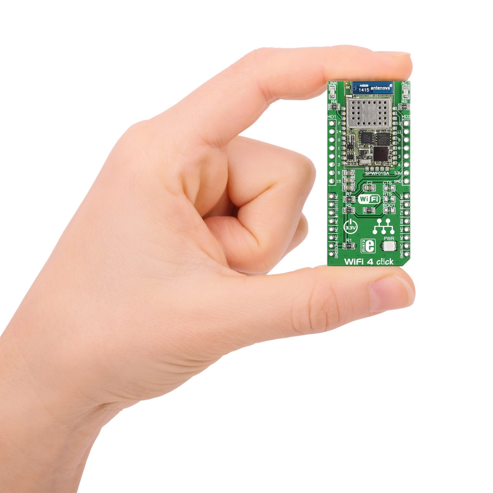
L (57.15 x 25.4 mm)
Input Voltage
3.3V
Pinout diagram
This table shows how the pinout on WiFi 4 Click corresponds to the pinout on the mikroBUS™ socket (the latter shown in the two middle columns).
Onboard settings and indicators
Label | Name | Default | Description |
---|---|---|---|
– | PWR | – | Power LED Indicator |
– | LINK | – | WiFi Link LED Indicator |
– | ACT | – | Active LED Indicator |
– | CTS | – | UART Clear To Send Input Jumper |
– | RTS | – | UART Request To Send Output Jumper |
– | BOOT | – | Bootloader Jumper |
WiFi 4 Click electrical specifications
Description | Min | Typ | Max | Unit |
---|---|---|---|---|
Supply Voltage | – | 3.3 | – | V |
Operating Frequency Range | – | 2.4 | – | GHz |
Data Rate | 1 | – | 54 | Mbps |
Transmit Power | – | 18.3 | – | dBm |