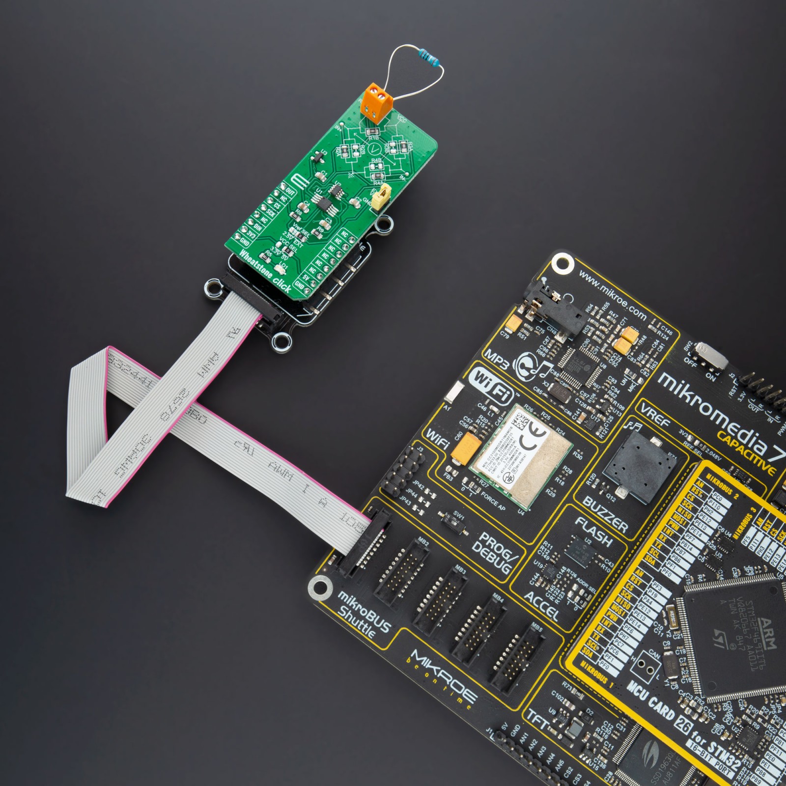
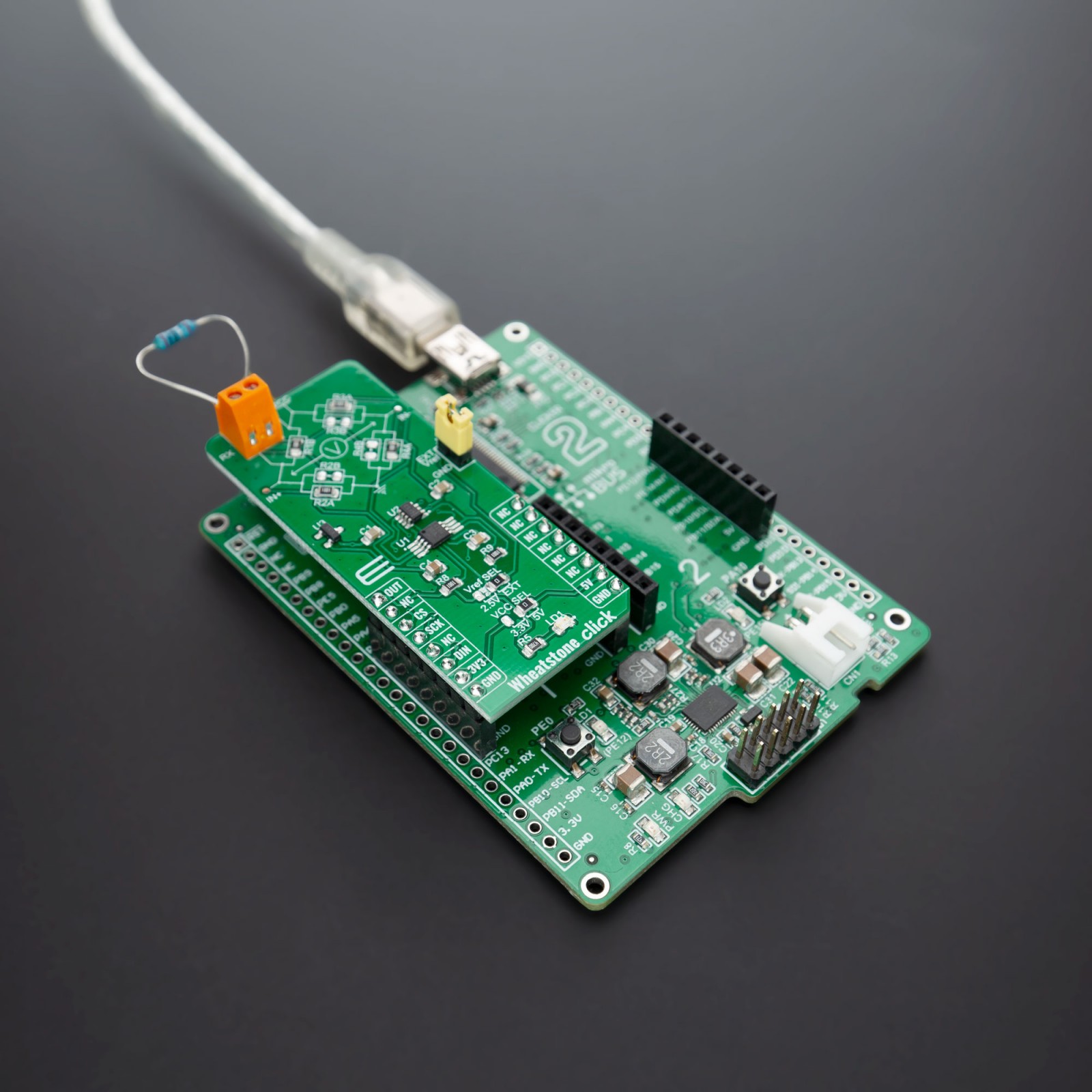
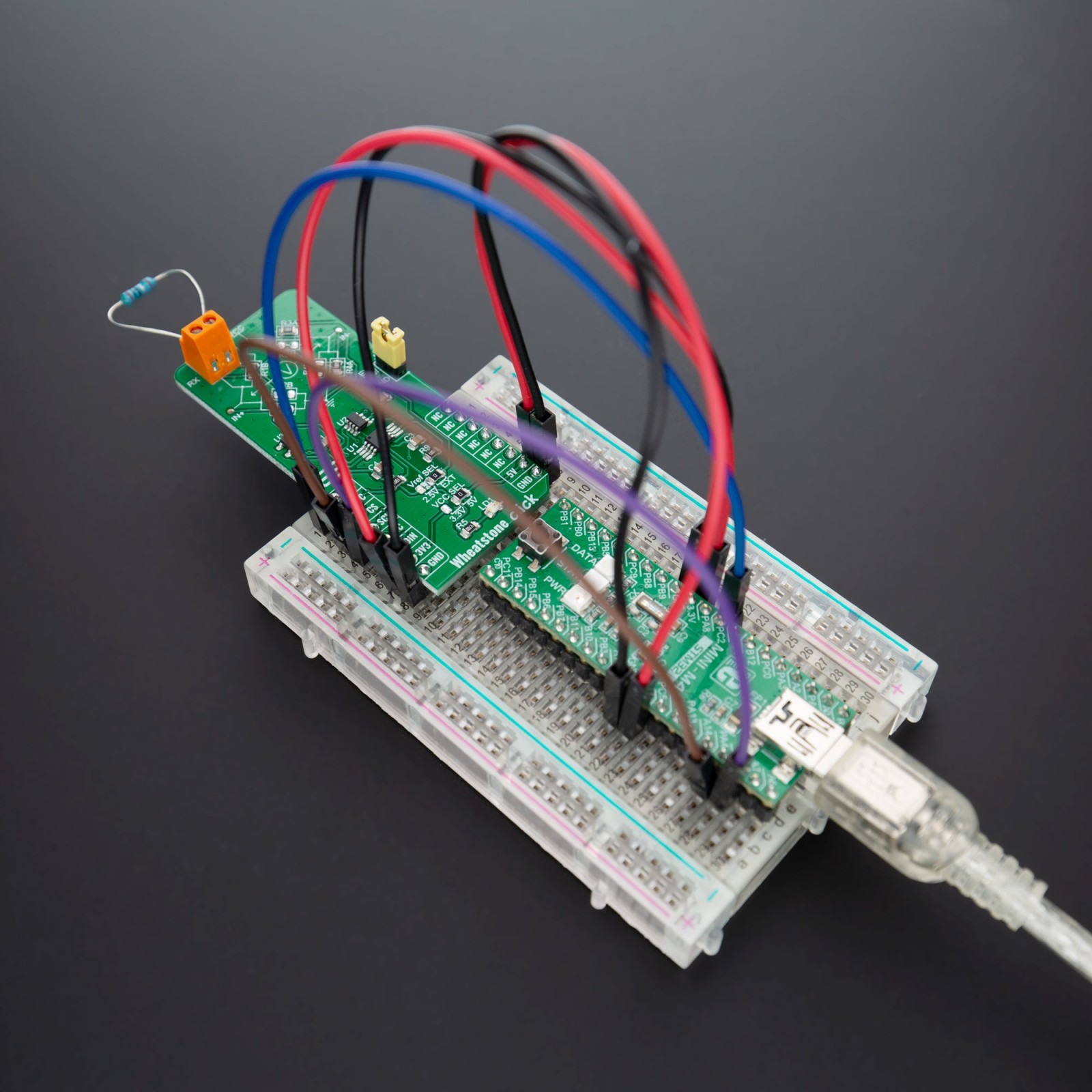
How does it work?
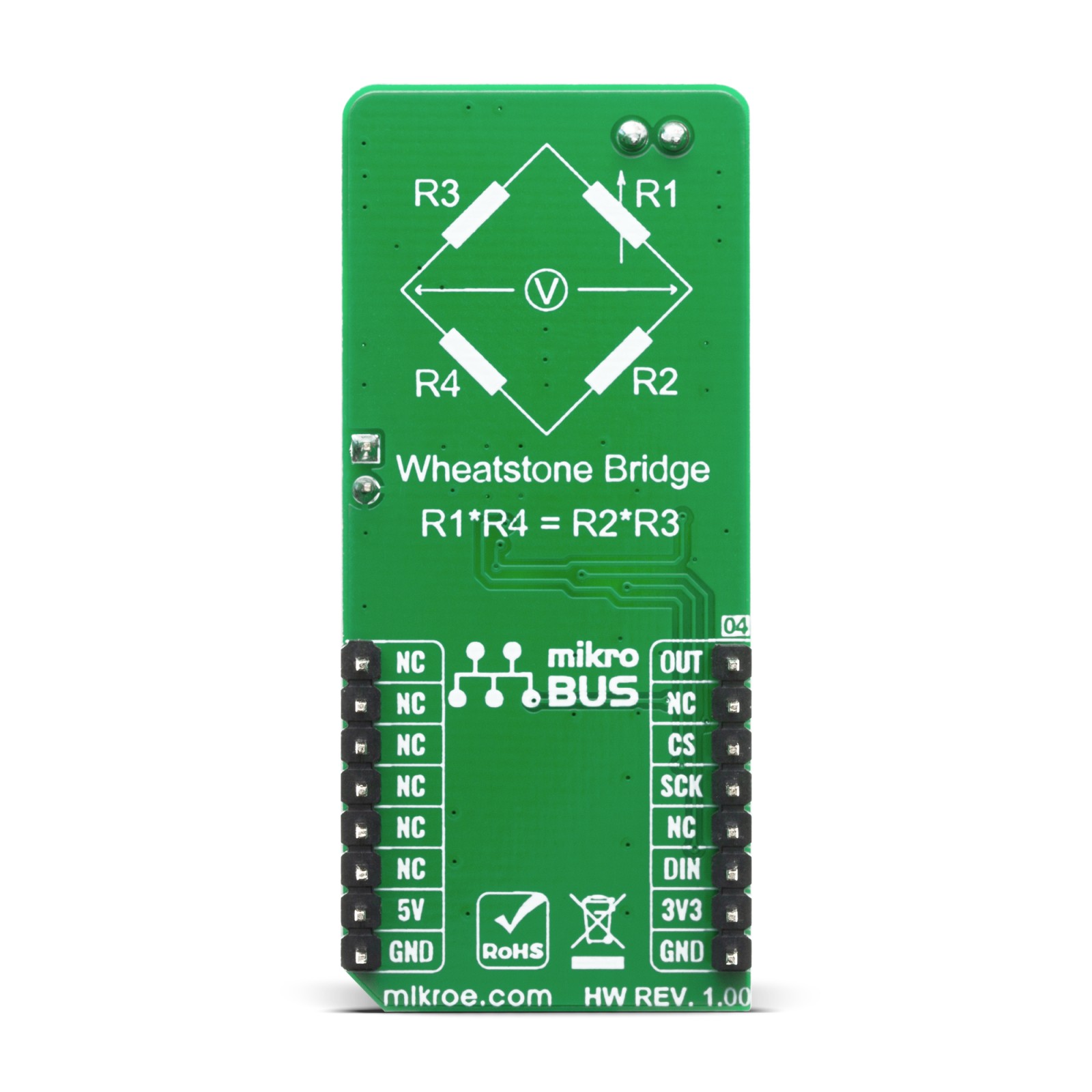
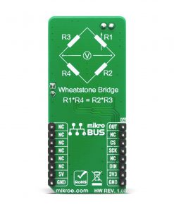
A Wheatstone bridge is an electrical circuit used to measure an unknown electrical resistance by balancing two branches of a bridge circuit, one branch of which includes the unknown component. The primary benefit of the circuit is its ability to provide extremely accurate measurements, in contrast with a simple voltage divider.
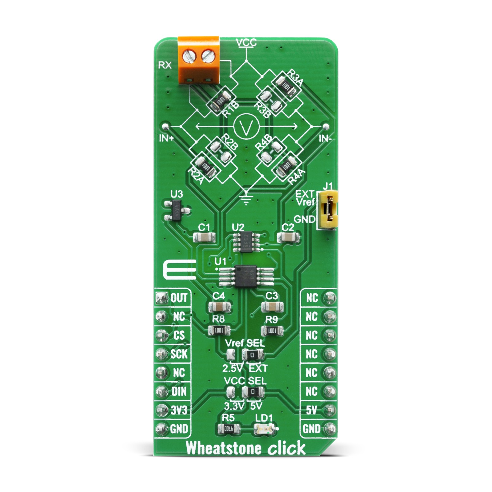
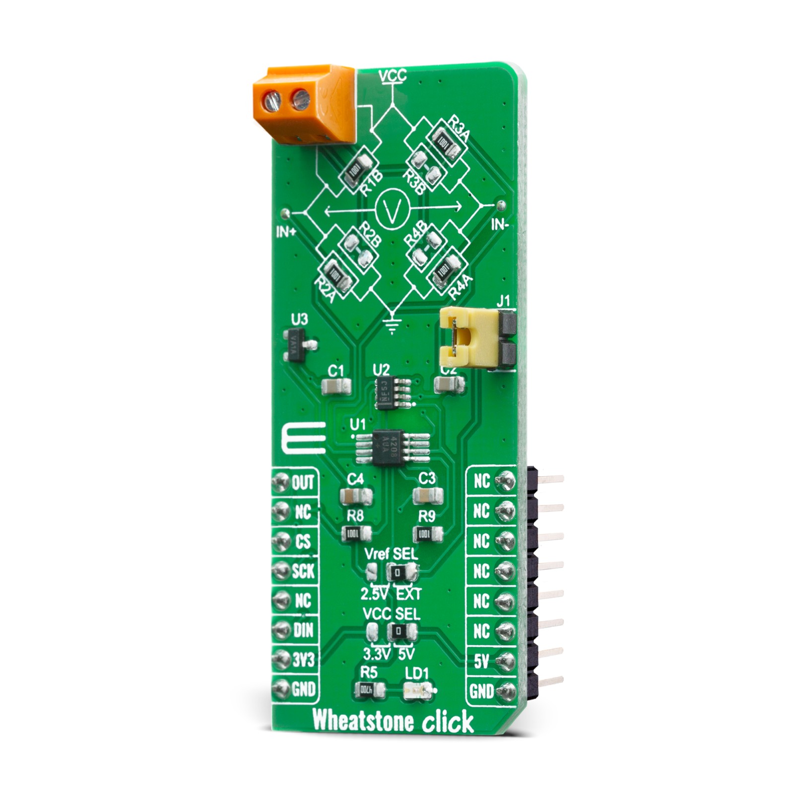
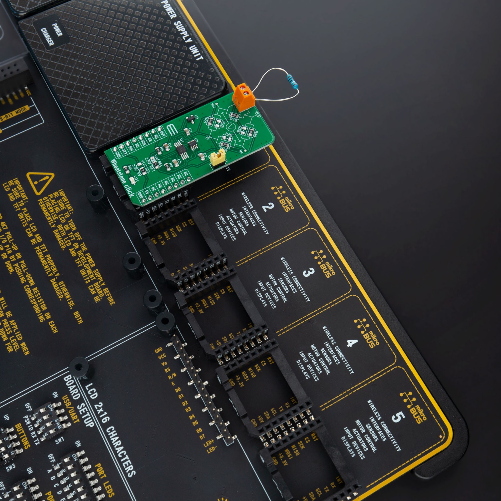
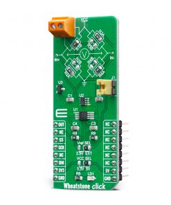
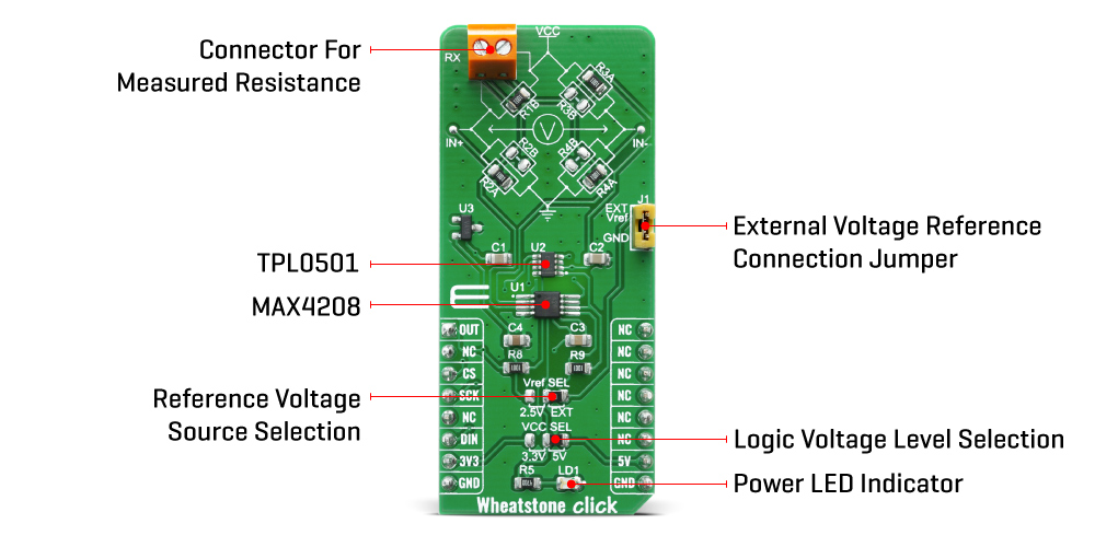
The R2, R3, and R4 are resistors of known resistance (1k ohm), while the resistance R1 is brought to the terminal block and therefore it is changeable. With no resistance connected to the terminal block, the bridge on this Click board™ is in balance. At this point, the voltage between the two midpoints (IN- and IN+) will be zero. Therefore the ratio of the two resistances in the known branch (R1 and R3) is equal to the ratio of the two resistances in the unknown leg (R2 and R4). If the external resistance is connected to the terminal block, bridge is unbalanced, and the voltage on the midpoints is proportional to the external resistor value.
Wheatstone click is based around the MAX4208 IC, which is connected to an onboard Wheatstone bridge circuit, in order to precisely measure the resistance of an external element. The mentioned IC uses a spreadspectrum, autozeroing technique that constantly measures and corrects the input offset, eliminating drift over time and temperature and the effect of 1/f noise. This technique achieves less than 20μV offset voltage, allows ground-sensing capability, provides ultra-low CMOS input bias current and increased common-mode rejection performance. It also provides high-impedance inputs, optimized for small-signal differential voltages (±100mV), which makes it ideal for an application such as wheatstone bridge disbalance measurement.
This Click board™ also has TPL0501 onboard – 256-Taps, Single-Channel, Digital Potentiometer With SPI Interface, from texas instruments. It is connected to the MAX4208 in a way that it serves an gain adjust instead of with two external resistors
The power supply voltage selection for the logic section is done by moving the SMD jumper labeled as VCC SEL to a desired position: left position to select 3.3V, right position to select 5V. This will allow both 3.3V and 5V MCUs to be interfaced with the Click board™ directly.
Specifications
Type
Measurements
Applications
Wheatstone click is ideal for using in various applications which may include sensor readings and precise resistance measurements.
On-board modules
MAX4208 – an ultra-low offset/drift, precision instrumentation amplifier, from Maxim Integrated
TPL0501 onboard – 256-Taps, Single-Channel, Digital Potentiometer With SPI Interface, from texas instruments
Key Features
ultra-low offset/drift, Spread-Spectrum, Auto-Zero, Low Offset Voltage Drift and more
Interface
Analog,SPI
Feature
No ClickID
Compatibility
mikroBUS™
Click board size
L (57.15 x 25.4 mm)
Input Voltage
3.3V or 5V
Pinout diagram
This table shows how the pinout on Wheatstone Click corresponds to the pinout on the mikroBUS™ socket (the latter shown in the two middle columns).
Onboard settings and indicators
Label | Name | Default | Description |
---|---|---|---|
PWR | PWR | – | Power LED Indicator |
VCC SEL | JP1 | Left | Logic voltage level selection: left position 3.3V, right position 5V |
VREF SEL | JP2 | Left | Reference voltage selection: left position 2.5V, right position EXT |
EXT VREF | JP1 | – | External reference voltage connection jumper |
RX | – | – | Load cell excitation voltage connector |
Software Support
We provide a library for the Wheatstone Click on our LibStock page, as well as a demo application (example), developed using MikroElektronika compilers. The demo can run on all the main MikroElektronika development boards.
Library Description
The library contains basic functions for working with Wheatstone click.
Key functions:
float wheatstone_get_voltage ( uint16_t adc_value )
– Get Voltagevoid wheatstone_set_adc_vref ( float vref )
– Set ADC VREFvoid wheatstone_set_adc_resolution ( float res )
– Set ADC resolution
Examples description
The application is composed of three sections :
- System Initialization – Initializes the SPI driver init all necessary GPIO pins
- Application Initialization – Initializes driver init and ADC module init – sets the ADC resolution, vref and potentiometer
- Application Task – Reads the ADC value and converts to voltage on the AN pin
- Note: Set the ADC resolution and vref before programming
void application_task ( ) { char demo_text[ 50 ]; float voltage; uint32_t adc_value = 0; adc_value = wheatstone_adc_read( ); IntToStr( adc_value, demo_text ); mikrobus_logWrite( "-- ADC value: ", _LOG_TEXT ); mikrobus_logWrite( demo_text, _LOG_LINE ); voltage = wheatstone_get_voltage( adc_value ); FloatToStr( voltage, demo_text ); mikrobus_logWrite( "-- Voltage: ", _LOG_TEXT ); mikrobus_logWrite( demo_text, _LOG_TEXT ); mikrobus_logWrite( "mV", _LOG_LINE ); mikrobus_logWrite( "---------------------", _LOG_LINE ); Delay_ms( 2000 ); }
The full application code, and ready to use projects can be found on our LibStock page.
Other mikroE Libraries used in the example:
- SPI Library
- ADC Library
- Conversions Library
Additional notes and informations
Depending on the development board you are using, you may need USB UART click, USB UART 2 click or RS232 click to connect to your PC, for development systems with no UART to USB interface available on the board. The terminal available in all MikroElektronika compilers, or any other terminal application of your choice, can be used to read the message.
mikroSDK
This Click board™ is supported with mikroSDK – MikroElektronika Software Development Kit. To ensure proper operation of mikroSDK compliant Click board™ demo applications, mikroSDK should be downloaded from the LibStock and installed for the compiler you are using.
For more information about mikroSDK, visit the official page.