Waveform 2 Click
R1,100.00 ex. VAT
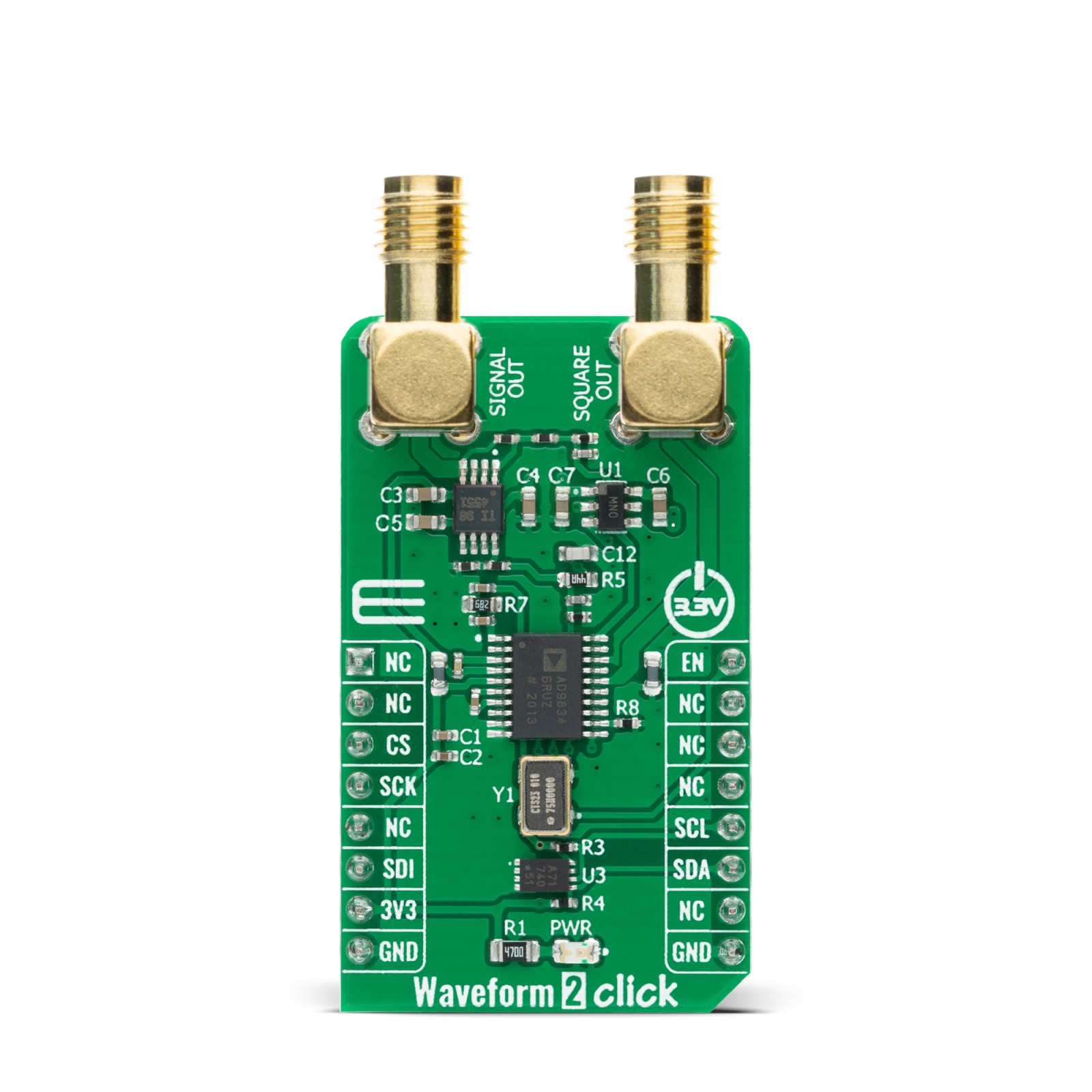
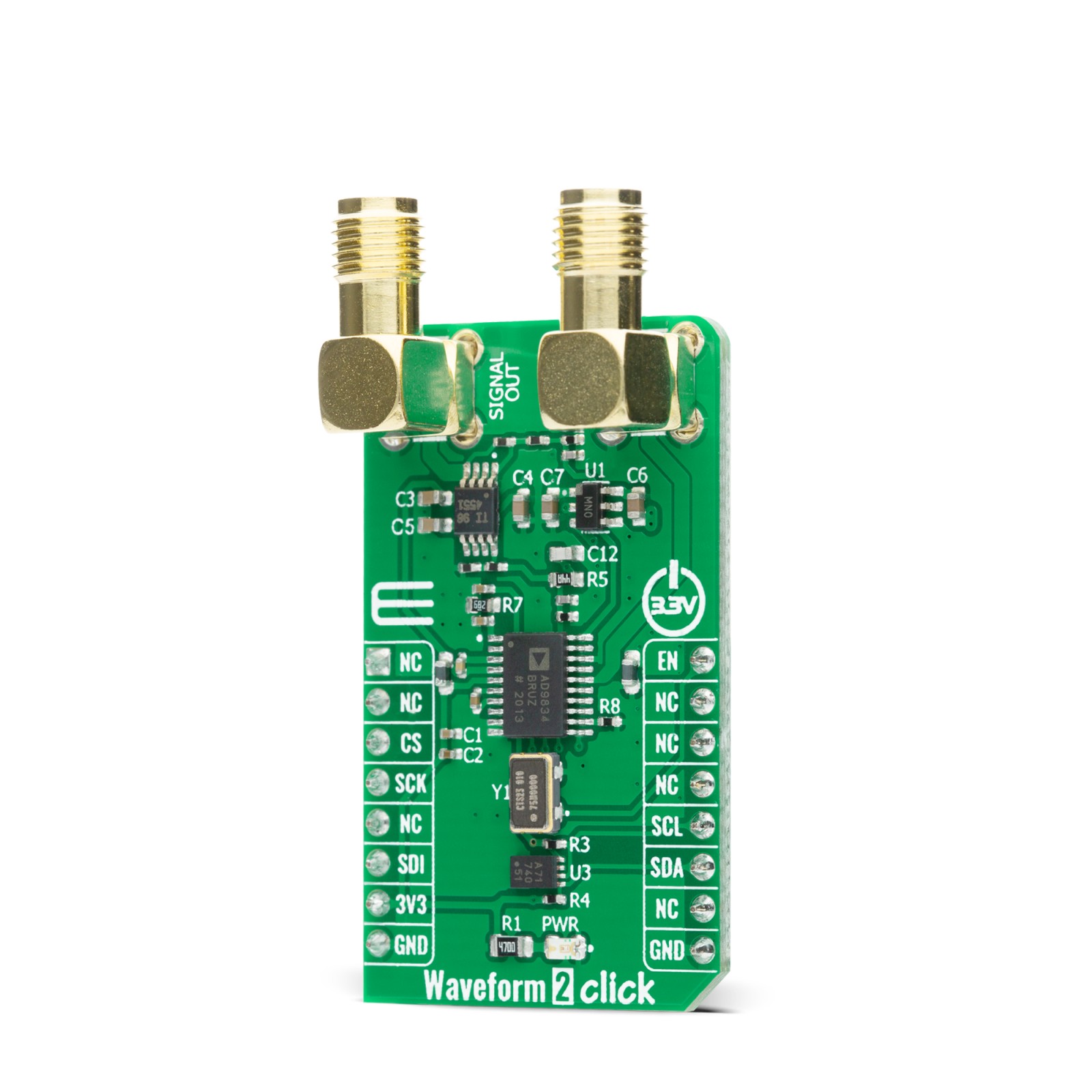
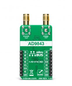
Waveform 2 Click is a compact add-on board that contains a direct digital synthesis device for waveform generator applications. This board features the AD9834, a 75 MHz low power DDS device capable of producing high-performance sine/triangle/square outputs from Analog Devices. It provides the capability for phase and frequency modulation and has an on-board comparator that allows the production of a square wave signal for clock generation. With a 75 MHz clock rate resolution of 0.28Hz can be achieved, while similarly, with a 1 MHz clock rate an AD9834 can be tuned to 0.004Hz resolution. This Click board™ represents an ideal candidate for power-sensitive applications, frequency stimulus/waveform generation, frequency phase tuning and modulation, and many more.
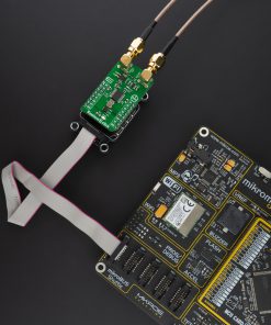
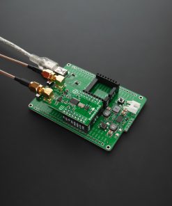
Waveform 2 Click is supported by a mikroSDK compliant library, which includes functions that simplify software development. This Click board™ comes as a fully tested product, ready to be used on a system equipped with the mikroBUS™ socket.
Stock: Lead-time applicable.
| 5+ | R1,045.00 |
| 10+ | R990.00 |
| 15+ | R935.00 |
| 20+ | R899.80 |
How does it work?
Waveform 2 Click is based on the AD9834, a 75 MHz low power DDS device capable of producing high-performance sine/triangle/square outputs from Analog Devices. The AD9834 is capable of a broad range of simple and complex modulation schemes. These modulation schemes are fully implemented in the digital domain, allowing the accurate realization of complex modulation algorithms using DSP techniques. It contains a 16-bit control register accessible through the SPI serial interface that sets up the AD9834 as the user wants to operate it. The internal circuitry of the AD9834 consists of a numerically controlled oscillator (NCO), frequency and phase modulators, SIN ROM, a DAC, a comparator, and a regulator.

The outputs of the AD9834 are filtered by an RC network and then amplified via THS4551, a fully differential amplifier that offers an easy interface from single-ended sources to the differential output required by high-precision analog-to-digital converters from Texas Instruments. The output signal from the AD9834 follows two paths. One path is routed to an output connector labeled as Signal Out when the output waveform of the generator is sinusoidal or triangular, while the other path, routed to an output connector labeled as Square Out, is used when the output waveform of the generator is square.
In addition to the positive supply voltage requirement, the THS4551 amplifier also has a negative supply voltage, which is achieved by the ADM8829, a charge-pump voltage inverter used to generate a negative supply from a positive input from Analog Devices. This Click board™ also has an external oscillator of 75 MHz, which can be enabled by the EN pin of the mikroBUS™ socket, and represents the maximum frequency that can be accepted by the AD9834. The 75MHz clock produces the cleanest possible Sine waveform at high frequencies while on the other creates errors at low frequencies. In addition to these features, the Waveform 2 Click also has an EEPROM memory IC the 24AA64, an i2C configurable 64K serial EEPROM from Microchip that can be used for various storage applications.
The Waveform 2 Click communicates with MCU using the 3-Wire SPI serial interface that is compatible with standard SPI, QSPI™, MICROWIRE™ and operates at clock rates up to 40 MHz. Besides. It possesses additional functionality such as reset function, necessary during AD9834 initialization, implemented and routed at the RST pin of the mikroBUS™ socket.
This Click board™ is designed to be operated only with a 3.3V logic voltage level. A proper logic voltage level conversion should be performed before the Click board™ is used with MCUs with different logic levels. However, the Click board™ comes equipped with a library that contains easy to use functions and an example code that can be used as a reference for further development.
Specifications
Type
Clock generator
Applications
Can be used for power-sensitive applications, frequency stimulus/waveform generation, frequency phase tuning and modulation, and many more.
On-board modules
Waveform 2 Click is based on the AD9834, a 75 MHz low power DDS device capable of producing high-performance sine/triangle/square outputs from Analog Devices.
Key Features
Low power consumption, high-performance sine/triangle/square outputs, capability for phase and frequency modulation, on-board comparator, and more.
Interface
I2C,SPI
Feature
No ClickID
Compatibility
mikroBUS™
Click board size
M (42.9 x 25.4 mm)
Input Voltage
3.3V
Pinout diagram
This table shows how the pinout on Waveform 2 Click corresponds to the pinout on the mikroBUS™ socket (the latter shown in the two middle columns).
Onboard settings and indicators
| Label | Name | Default | Description |
|---|---|---|---|
| LD1 | PWR | – | Power LED Indicator |
| CN1 | SIGNAL OUT | – | Sinusoidal/Triangular Output Signal |
| CN2 | SQUARE OUT | – | Square Output Signal |
Waveform 2 Click electrical specifications
| Description | Min | Typ | Max | Unit |
|---|---|---|---|---|
| Supply Voltage | -0.3 | 3.3 | 3.6 | V |
| Maximum Output Current | – | 3 | 4 | mA |
| Maximum Output Frequency (with 75Hz EXT clock) | – | 25 | – | Hz |
| Resolution | – | 10 | – | bits |
| Update Rate | – | – | 75 | MSPS |
| Operating Temperature Range | -40 | – | +105 | °C |
Software Support
We provide a library for the Waveform 2 Click on our LibStock page, as well as a demo application (example), developed using MikroElektronika compilers. The demo can run on all the main MikroElektronika development boards.
Library Description
Library contains generic functions for working with the Waveform 2 Click™ board.
Key functions:
void waveform2_set_freq ( uint32_t freq )– Function for setting the output frequency.void waveform2_sine_output ( void )– Function for setting the sine output.void waveform2_triangle_output ( void )– Function for setting the triangle output.
Examples description
The application is composed of three sections :
- System Initialization – Initialize the GPIO and communication structures.
- Application Initialization – Initialize the communication interface and configure the Click board™.
- Application Task – Predefined characters are inputed from the serial port. Depending on the character sent the signal frequency, waveform or amplitude will be changed.
- Command: [ + ] – Increase frequency [ – ] – Decrease frequency [ t ] – Triangle-shaped signal [ s ] – The signal in the form of a sinusoid
void application_task ( )
{
    char rx_data;
    uint32_t freq_data;

    if ( UART_Rdy_Ptr( ) )
    {
       rx_data = UART_Rd_Ptr( );
    }

    if ( rx_data > 0 )
    {
        switch ( rx_data )
        {
            case '+':
            {
                f += 10;
                freq_data = f << 14;
                waveform2_set_freq( freq_data );
                rx_data = 0;
                mikrobus_logWrite( ">> Increasing the frequency ", _LOG_LINE );
                break;
            }

            case '-':
            {
                if ( f <= 9 )
                {
                    f = 0;
                }
                f -= 10;
                freq_data = f << 14;
                waveform2_set_freq( freq_data );
                rx_data = 0;
                mikrobus_logWrite( ">> Decreasing the frequency ", _LOG_LINE );
                break;
            }

            case 't':
            {
                waveform2_triangle_output( );
                rx_data = 0;
                mikrobus_logWrite( ">> Triangle output ", _LOG_LINE );
                break;
            }

            case 's':
            {
                waveform2_sine_output( );
                rx_data = 0;
                mikrobus_logWrite( ">> Sinusoid output ", _LOG_LINE );
                break;
            }
        }
    }
    rx_data = 0;
}
Additional Functions : aprox_freq_calculation( ) – This function is used to calculate the aproximate value that will be written to the frequency set register.
The full application code, and ready to use projects can be found on our LibStock page.
Other mikroE Libraries used in the example:
- UART Library
- I2C Library
- SPI Library
- Conversions Library
Additional notes and informations
Depending on the development board you are using, you may need USB UART click, USB UART 2 click or RS232 click to connect to your PC, for development systems with no UART to USB interface available on the board. The terminal available in all MikroElektronika compilers, or any other terminal application of your choice, can be used to read the message.
mikroSDK
This Click board™ is supported with mikroSDK – MikroElektronika Software Development Kit. To ensure proper operation of mikroSDK compliant Click board™ demo applications, mikroSDK should be downloaded from the LibStock and installed for the compiler you are using.
For more information about mikroSDK, visit the official page.
Resources
Downloads
| Weight | 28 g |
|---|---|
| Brand | MikroElektronika |

