Water Detect Click
R195.00 ex. VAT
Avoid plumbing and water leakage disasters
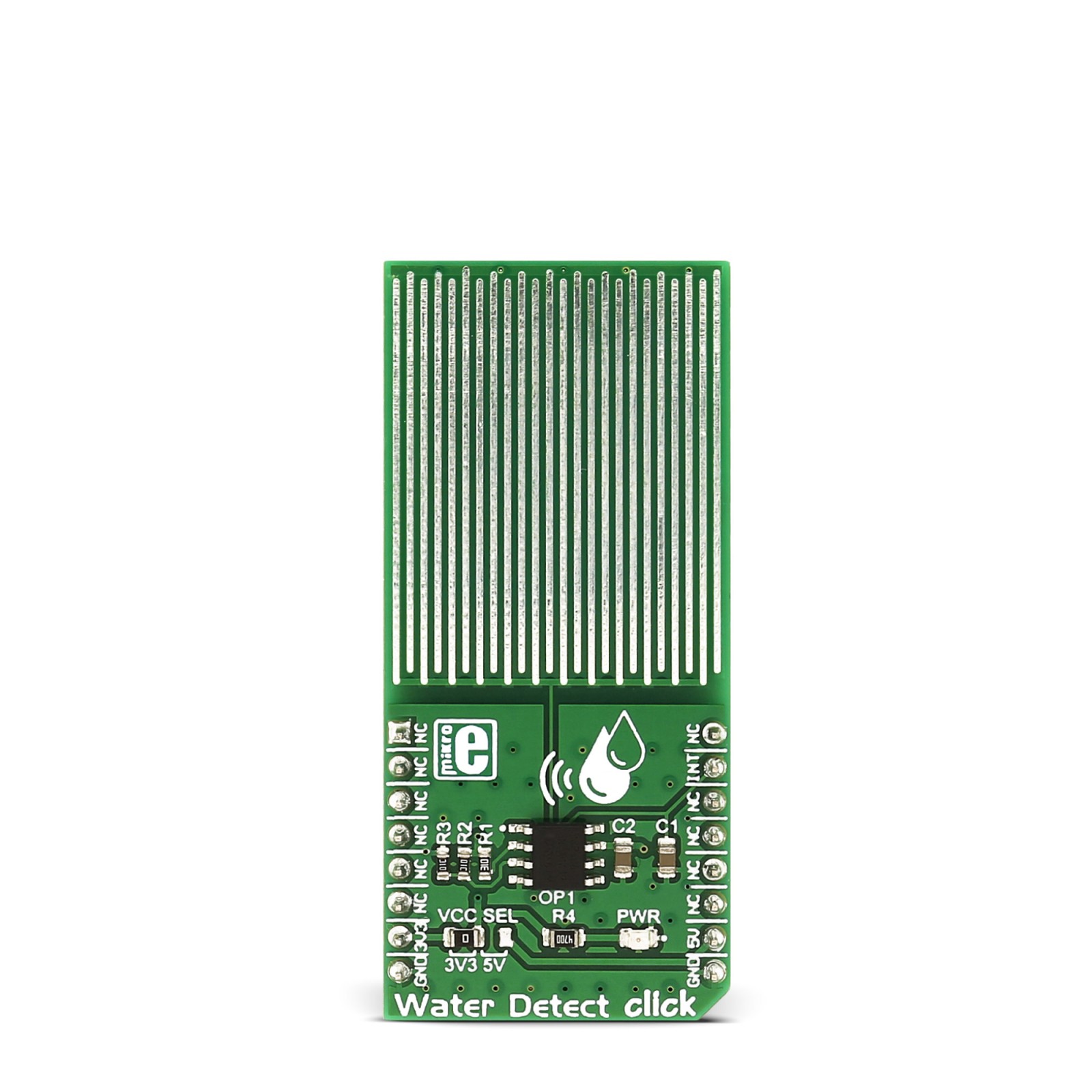
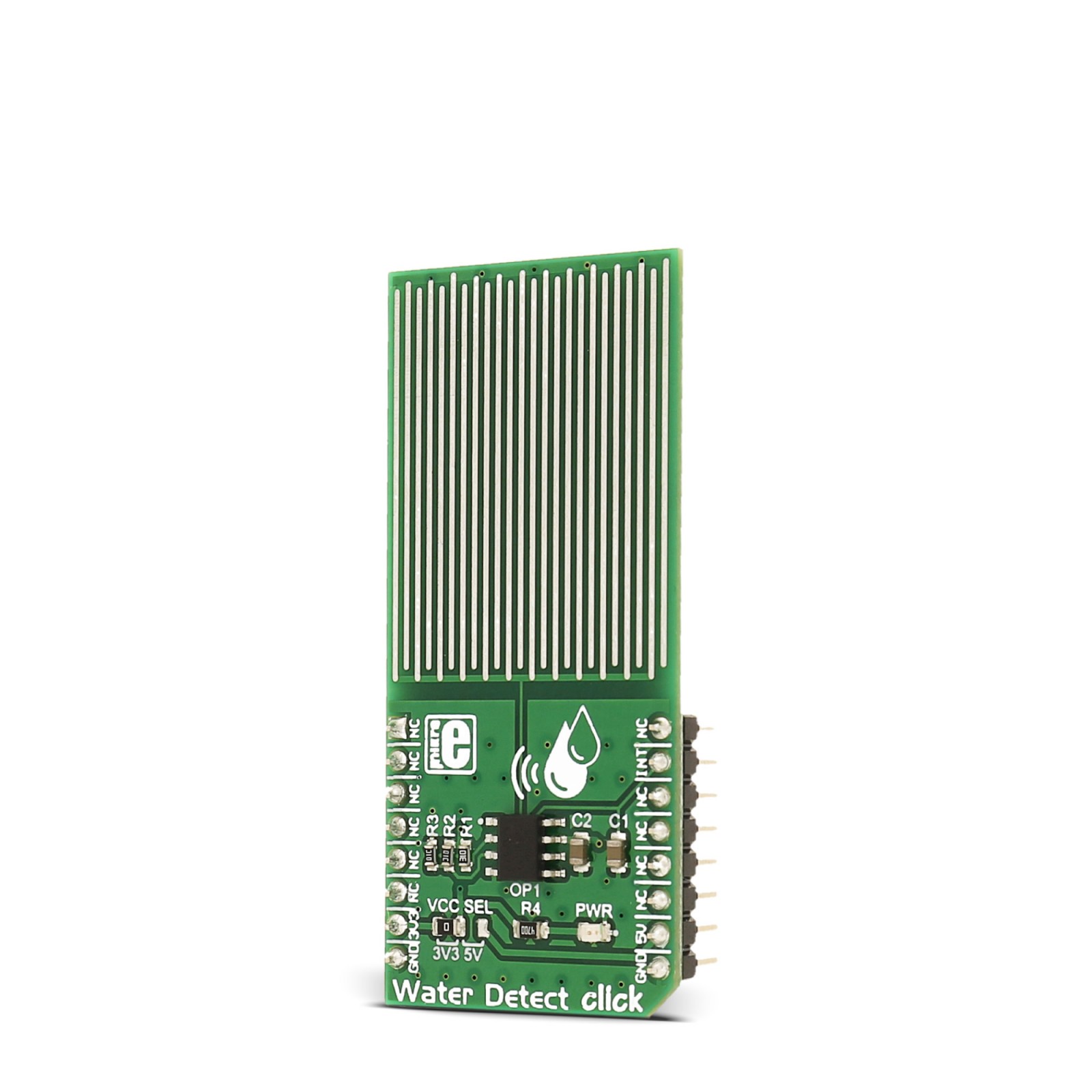
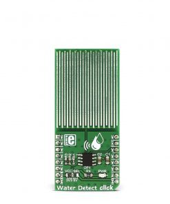
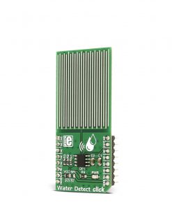
Water Detect click is used for detecting water and other electroconductive liquids. If the detection area is wet the output of Microchip’s MCP606 CMOS op-amp will go positive, signaling the presence of liquid.
Water Detect click can be used as a household flood alarm sensor, rain detector for smart buildings or for water tanks that act as a limit switch for a pump.
Stock: Lead-time applicable.
| 5+ | R185.25 |
| 10+ | R175.50 |
| 15+ | R165.75 |
| 20+ | R159.51 |
Water Detect click is used for detecting water and other electroconductive liquids. If the detection area is wet the output of Microchip’s MCP606 CMOS op-amp will go positive, signaling the presence of liquid.
Water Detect click can be used as a household flood alarm sensor, rain detector for smart buildings or for water tanks that act as a limit switch for a pump.
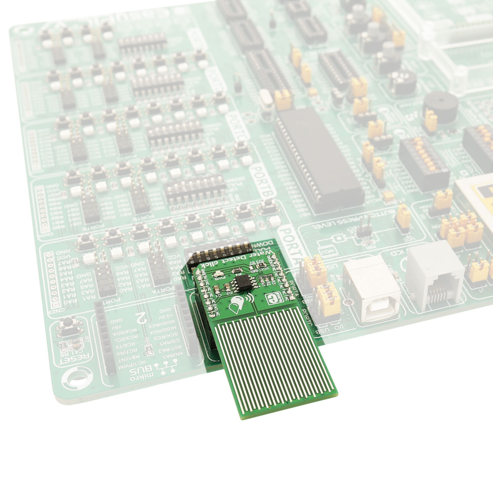
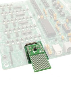
You could use it on one of our clicker 2 development boards, with GSM 4 click, or any other from the wireless range, and create a home flood alarm. Any time Water Detect click detects water it will send you an SMS.
How the click works
Water Detect click works by comparing the voltage of two resistor dividers using the MCP606 comparator. The resistor divider (made of R2 and R3) is used as a voltage reference.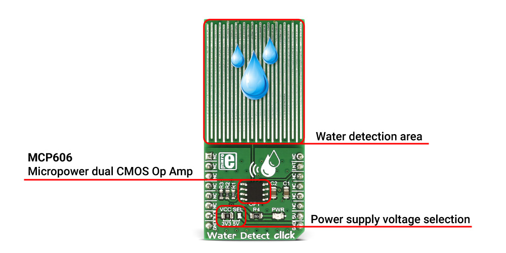
The MCP606 functions as a comparator on this click board™.
The second divider is made of resistor R1 and the sensory area. When the sensory area is dry, it’s resistance is near infinite, and the voltage applied to the inverting terminal of the comparator equals VCC.
Since the voltage of the reference divider connected to the non-inverting input is VCC/2, the output of the comparator is at zero voltage. Once the liquid is present at the sensory area, it’s resistance drops and pulls the voltage on the inverting input of the comparator toward zero volts. Once this voltage falls below VCC/2, the comparator output swings toward VCC signaling the presence of liquid. The comparator output is tied to the INT pin on the mikroBUS™ header.
The water detection area is actually made of exposed conducting wires – simple but effective technology.
Specifications
Type
Miscellaneous
Applications
Household flood alarm sensor, rain detector for smart buildings or water tank fill sensor, automated watering systems, etc.
On-board modules
Water detection area, MCP606 comparator
Key Features
The water detection area is actually made of exposed conducting wires – simple but effective technology
Interface
GPIO
Feature
No ClickID
Compatibility
mikroBUS™
Click board size
L (57.15 x 25.4 mm)
Input Voltage
3.3V or 5V
Pinout diagram
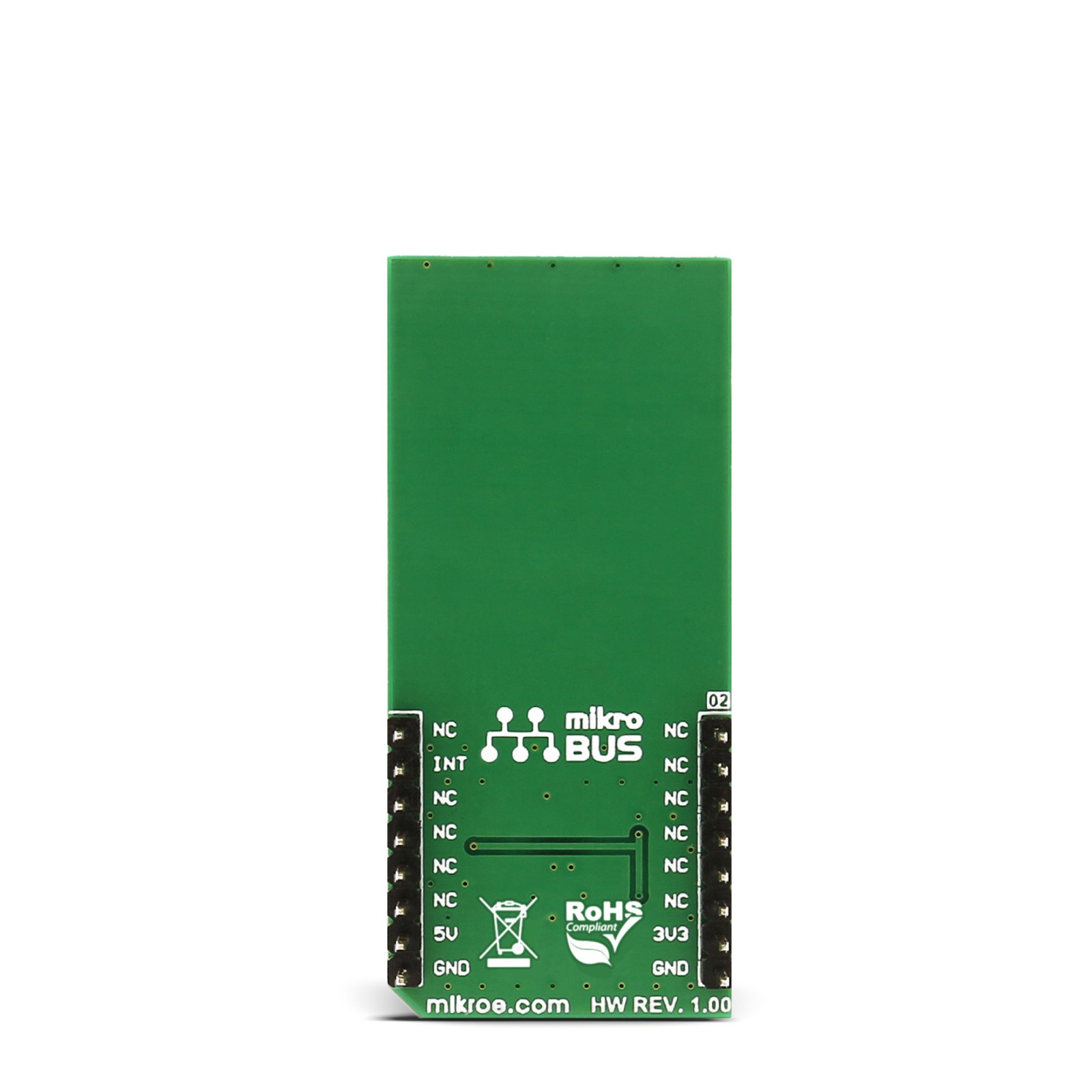
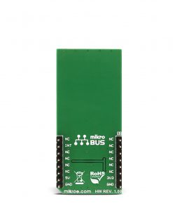
This table shows how the pinout on Water Detect click corresponds to the pinout on the mikroBUS™ socket (the latter shown in the two middle columns).
Jumpers and settings
| Designator | Name | Default Position | Default Option | Description |
|---|---|---|---|---|
| VCC SEL | VCC SEL | Left | 3.3V | Power Supply Voltage Selection between 3.3V/5V, left position 3.3V, right position 5V |
Software Support
We provide a library that reads the status of the click output (INT pin) when water is detected, as well as an example application that, when this happens, sends the message “Water detected!” on the microcontroller UART. The library and the example run on all the MikroElektronika compilers and main development boards; you can download both on LibStock.
Note: depending on the development board you are using, you may need the RS232 click or USB-UART click, to connect to your PC. The terminal available in all Mikroelektronika compilers, or any other of your choice, can be used to read the message.
Library Description
The library implements GPIO HAL and one function which checks the state of the INT pin.
Key functions:
uint8_t WDETECT_getStatus()- Returns water detection status
Demo application description
The demo application is composed of three sections :
- System Initialization - Initializes GPIO and UART used for logging
- Application Initialization - Initializes Library GPIO HAL
- Application Task - (code snippet) Constantly polling INT pin using
WDETECT_getStatus()if water is detected it sends a message to UART. It uses thegetINT()function which returns the state of INT pin.
void applicationTask()
{
    if (WDETECT_getStatus())
    {
        UART1_Write_text("Water Detected!");
        UART1_Write(13);
        UART1_Write(10);
    }
}
Other MikroElektronika Libraries used in this demo application:
- UART
The full application code and libraries are available for download on our LibStock page.
Resources
Downloads
| Weight | 22 g |
|---|---|
| Brand | MikroElektronika |

