How does it work?
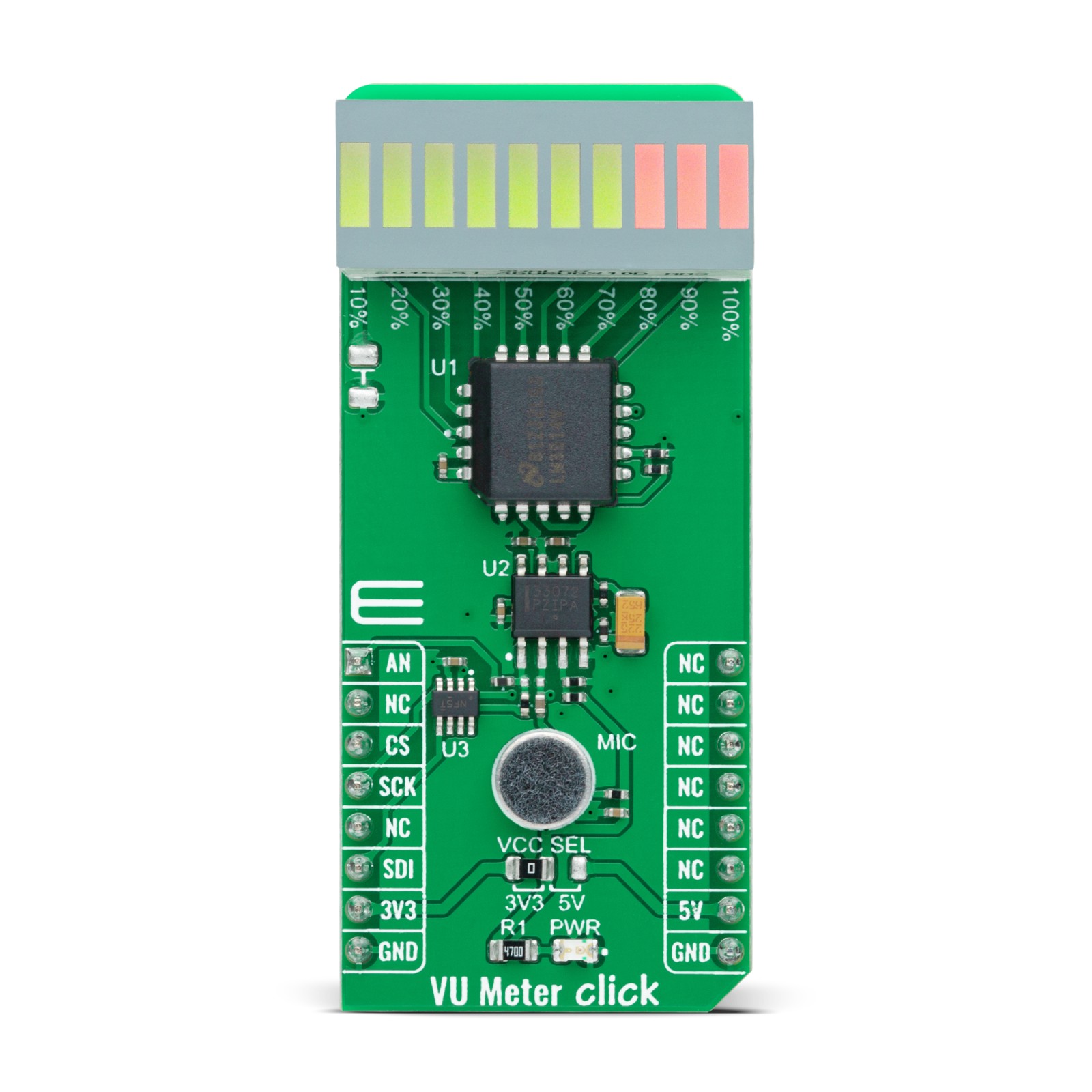
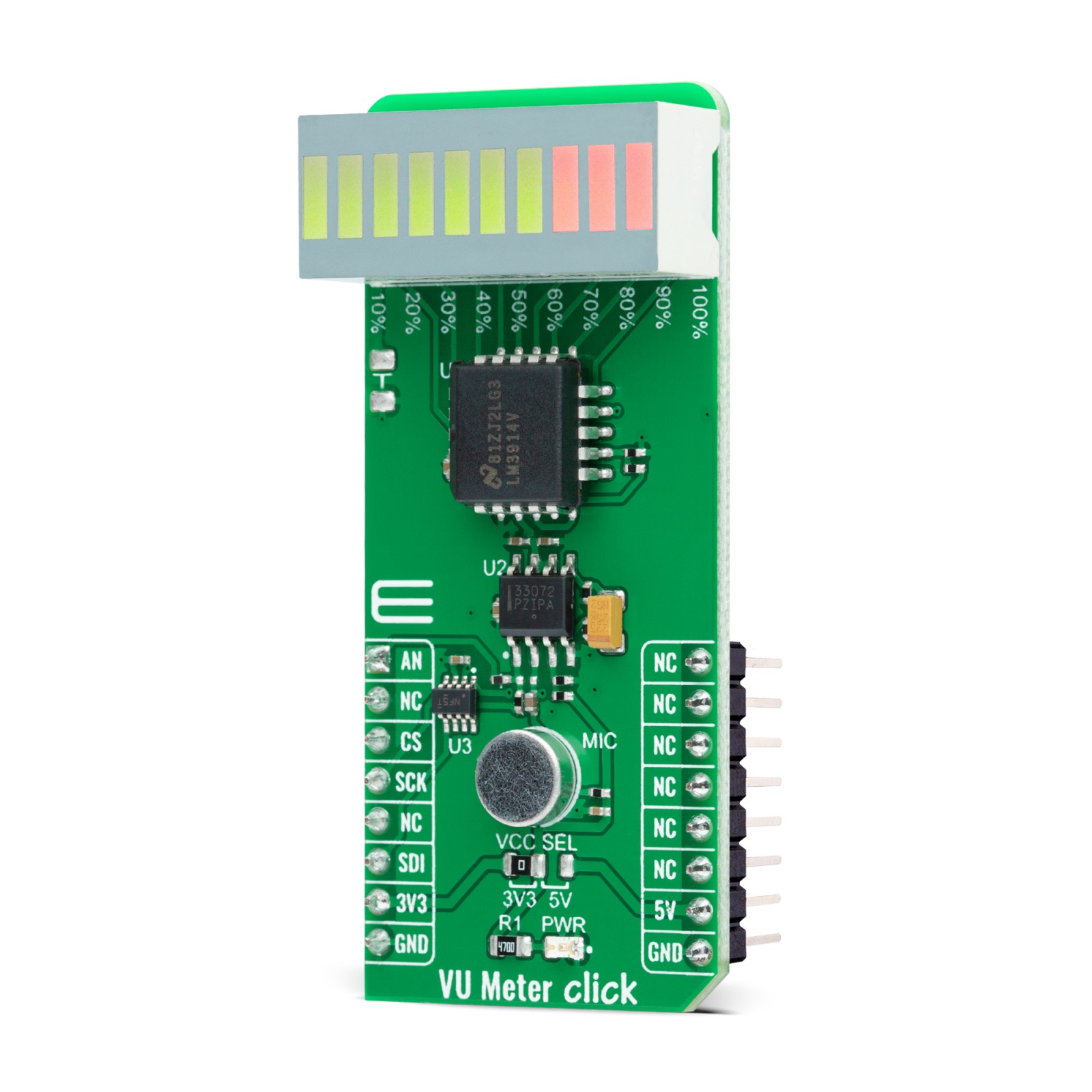
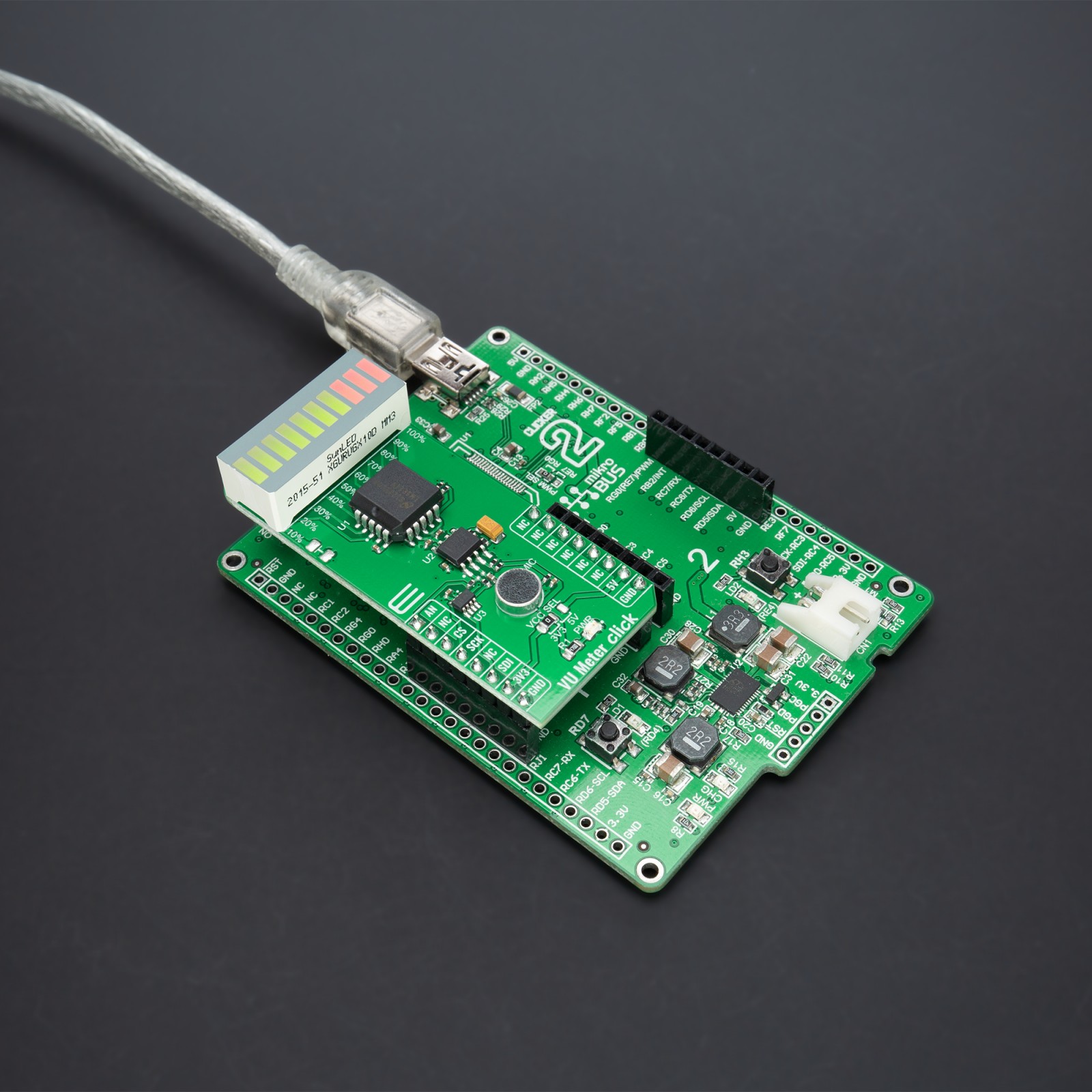
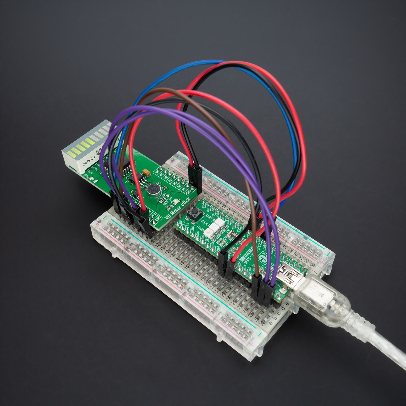
VU Meter Click as its foundation uses the LM3914, a monolithic integrated circuit that senses analog voltage levels and drives a 10-segment bar graph display from Texas Instruments, making this solution a compact volume unit meter. This is an analog-controlled driver meaning it can control display by an analog input voltage and eliminates the need for additional programming. A volume unit meter represents a device that displays the intensity of an audio signal; more specifically, it is used to visualize analog signals. That’s why VU Meter Click is suitable as a volume measurement gadget.
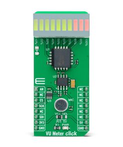
The LM3914 is configured to work in bar mode where all parts of the bar graph display below a certain point turn on. This board is manufactured with an onboard sound detecting device (microphone), the MC33072 Op-Amp, and the LM3914, which gleams the bar graph display according to the sound’s quality. In the beginning, the microphone captures the sound and transforms it into voltages linear to sound amplitude. The capacitor then stops the DC component of the transmission, allowing the AC input from the microphone to enter the MC33072 Op-Amp.
One part of the MC33072 represents a variable gain inverting amplifier using the TPL0501, an SPI-configurable digital potentiometer from Texas Instruments, while the second part represents a signal buffer. After filtration and amplification, these filtered and amplified signals are finally provided to LM3914. Considering that this driver is analog controlled, this Click board™ also provides the ability to monitor the analog signal by the MCU via the AN pin of the mikroBUS™ socket.
The LM3914 operates in a voltmeter format and lights the XGURUGX10D, a ten-segment bar graph array, according to the strength of the given signal. The onboard bar graph display segments are bright and uniformly colored, providing pleasant and clean visual feedback. Each segment is composed of green and red-colored LEDs, making it possible to have various essential states marked in a different color. It can use green, red, and a combination of these two, resulting in having amber-colored segments.
This Click board™ can operate with both 3.3V and 5V logic voltage levels selected via the VCC SEL jumper. This way, it is allowed for both 3.3V and 5V capable MCUs to use the communication lines properly. However, the Click board™ comes equipped with a library that contains easy-to-use functions and an example code that can be used, as a reference, for further development.
Specifications
Type
Microphone
Applications
Can be used in visual alarms and other metering or monitoring applications
On-board modules
LM3914 – monolithic integrated circuit that senses analog voltage levels and drives a 10-segment bar graph display from Texas Instruments
Key Features
Analog controlled driver, bar operation mode, programmable output current, low power consumption, and more
Interface
Analog,SPI
Feature
No ClickID
Compatibility
mikroBUS™
Click board size
L (57.15 x 25.4 mm)
Input Voltage
3.3V or 5V
Pinout diagram
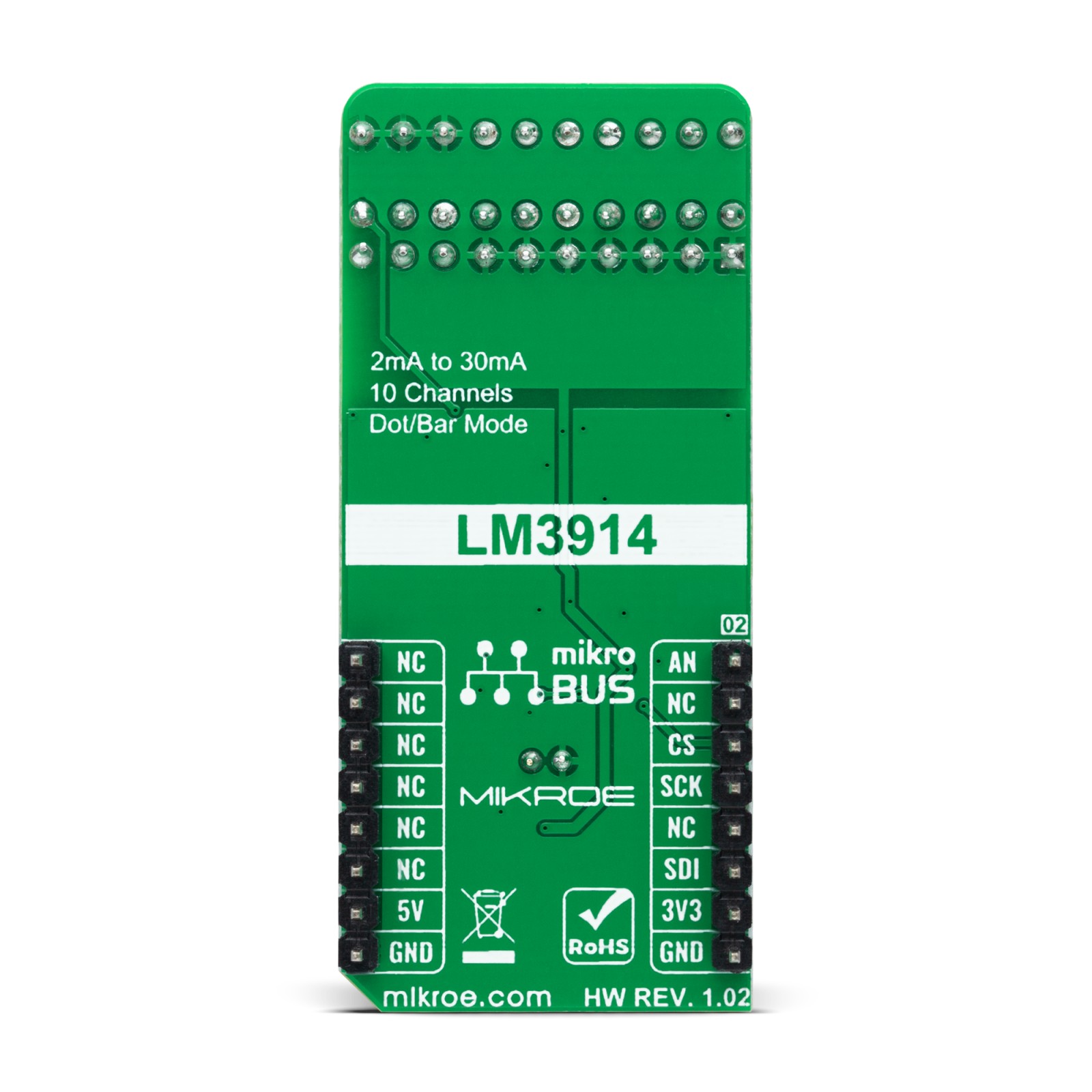
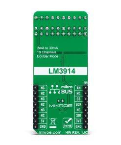
This table shows how the pinout on VU Meter Click corresponds to the pinout on the mikroBUS™ socket (the latter shown in the two middle columns).
Onboard settings and indicators
Label | Name | Default | Description |
---|---|---|---|
LD1 | PWR | – | Power LED Indicator |
JP1 | VCC SEL | Left | Logic Level Voltage Selection 3V3/5V: Left position 3V3, Right position 5V |
VU Meter Click electrical specifications
Description | Min | Typ | Max | Unit |
---|---|---|---|---|
Supply Voltage | 3.3 | – | 5 | V |
Maximum Output Current | 2 | 10 | 30 | mA |
Operating Temperature Range | 0 | +25 | +70 | °C |
Software Support
We provide a library for the VU Meter Click as well as a demo application (example), developed using MikroElektronika compilers. The demo can run on all the main MikroElektronika development boards.
Package can be downloaded/installed directly from NECTO Studio Package Manager(recommended way), downloaded from our LibStock™ or found on Mikroe github account.
Library Description
This library contains API for VU Meter Click driver.
Key functions
-
vumeter_read_an_pin_voltage
This function reads results of AD conversion of the AN pin and converts them to proportional voltage level. -
vumeter_set_gain_level
This function sets the input signal gain level (the microphone sensitivity). -
vumeter_calculate_vu_level
This function calculates VU level from the analog voltage input.
Example Description
This example demonstrates the use of VU Meter Click board™.
void application_task ( void )
{
log_printf( &logger, " VU level: %.3f VUrn", vumeter_calculate_vu_level ( &vumeter, 100 ) );
}
The full application code, and ready to use projects can be installed directly from NECTO Studio Package Manager(recommended way), downloaded from our LibStock™ or found on Mikroe github account.
Other Mikroe Libraries used in the example:
- MikroSDK.Board
- MikroSDK.Log
- Click.VUMeter
Additional notes and informations
Depending on the development board you are using, you may need USB UART click, USB UART 2 Click or RS232 Click to connect to your PC, for development systems with no UART to USB interface available on the board. UART terminal is available in all MikroElektronika compilers.
mikroSDK
This Click board™ is supported with mikroSDK – MikroElektronika Software Development Kit. To ensure proper operation of mikroSDK compliant Click board™ demo applications, mikroSDK should be downloaded from the LibStock and installed for the compiler you are using.
For more information about mikroSDK, visit the official page.