How does it work?
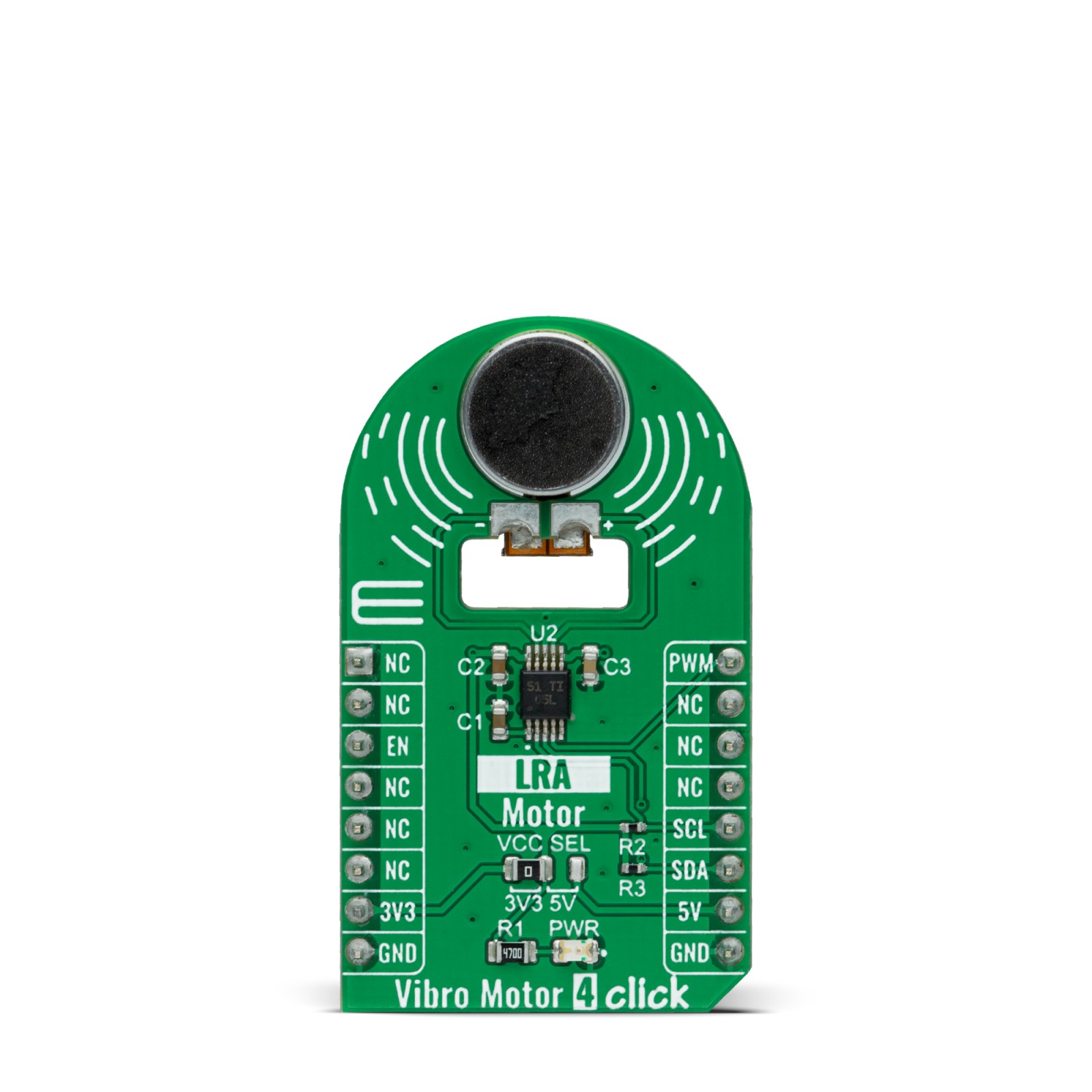
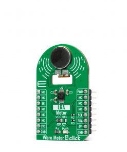
Vibro Motor 4 Click as its foundation uses the VG1040003D, coin-sized linear resonant actuator that generates vibration/haptic feedback in the Z plane perpendicular to the motor’s surface from Vybronics. The VG1040003D draws a typical 145mA while producing a G force of 2 GRMS and makes an excellent choice for applications requiring crisp haptic feedback and low power consumption. For haptic feedback applications, fast rise and fall times are critical for achieving the optimal user experience. That’s why the rise time (50% power) of the G1040003D, which is 10ms, and its fall time (10% power) of 50ms makes it one of the best choices for haptic feedback applications.
Driven by the DRV2605, a flexible Haptic/Vibra driver from Texas Instruments, this Click board™ is designed to provide highly flexible haptic control over a standard I2C 2-Wire interface with a maximum clock frequency of 400kHz. It possesses enabling function, routed on the CS pin of the mikroBUS™ socket labeled as the EN, and comes up with an extensive integrated library of over 100 licensed effects that eliminates the need to design haptics waveforms. It also contains a smart-loop architecture and provides automatic overdrive and braking, creating a simplified input waveform paradigm, reliable motor control, and consistent motor performance.
Additionally, the DRV2605 can also operate in the PWM Mode and accept the PWM signal from the PWM pin of the mikroBUS™ socket. In this mode, the DRV2605 device drives the actuator continuously until the user sets the DRV2605 to a Standby Mode or enters another interface mode. More information about the operating modes of the DRV2605 can be found in the attached datasheet.
This Click board™ can operate with both 3.3V and 5V logic voltage levels selected via the VCC SEL jumper. This way, it is allowed for both 3.3V and 5V capable MCUs to use the I2C communication lines properly. However, the Click board™ comes equipped with a library containing easy-to-use functions and an example code that can be used, as a reference, for further development.
Specifications
Type
Haptic
Applications
Can be used for devices with limited battery capacity and for users who require crisp haptic feedback and low power consumption
On-board modules
VG1040003D – coin-sized linear resonant actuator that generates vibration/haptic feedback in the Z plane perpendicular to the motor’s surface from Vybronics
Key Features
Low power consumption, vibration force in Z-axis, high reliability, excellent choice for devices with limited battery capacity, and more
Interface
I2C,PWM
Feature
No ClickID
Compatibility
mikroBUS™
Click board size
M (42.9 x 25.4 mm)
Input Voltage
3.3V or 5V
Pinout diagram
This table shows how the pinout on Vibro Motor 4 Click corresponds to the pinout on the mikroBUS™ socket (the latter shown in the two middle columns).
Onboard settings and indicators
Label | Name | Default | Description |
---|---|---|---|
LD1 | PWR | – | Power LED Indicator |
JP1 | VCC SEL | Left | Logic Level Voltage Selection 3V3/5V: Left position 3V3, Right position 5V |
Vibro Motor 4 Click electrical specifications
Description | Min | Typ | Max | Unit |
---|---|---|---|---|
Supply Voltage | 3.3 | – | 5 | V |
Maximum Output Current | – | 145 | 170 | mA |
Vibration G Force | – | – | 2 | GRMS |
Operating Temperature Range | -25 | +25 | +70 | °C |
Software Support
We provide a library for the Vibro Motor4 Click as well as a demo application (example), developed using MikroElektronika compilers. The demo can run on all the main MikroElektronika development boards.
Package can be downloaded/installed directly from NECTO Studio Package Manager(recommended way), downloaded from our LibStock™ or found on Mikroe github account.
Library Description
This library contains API for Vibro Motor 4 Click driver.
Key functions:
vibromotor4_cfg_setup
– Config Object Initialization function.vibromotor4_init
– Initialization function.vibromotor4_default_cfg
– Click Default Configuration function.
Example description
This library contains API for Vibro Motor 4 Click driver. The library initializes and defines the I2C bus drivers to write and read data from registers and PWM module.
void application_task ( void ) { static int8_t duty_cnt = 0; static int8_t duty_inc = 1; float duty = duty_cnt / 10.0; vibromotor4_set_duty_cycle ( &vibromotor4, duty ); log_printf( &logger, "> Duty: %d%%rn", ( uint16_t )( duty_cnt * 10 ) ); Delay_ms( 1000 ); if ( 5 == duty_cnt ) { duty_inc = -1; } else if ( 0 == duty_cnt ) { duty_inc = 1; } duty_cnt += duty_inc; }
The full application code, and ready to use projects can be installed directly from NECTO Studio Package Manager(recommended way), downloaded from our LibStock™ or found on Mikroe github account.
Other Mikroe Libraries used in the example:
- MikroSDK.Board
- MikroSDK.Log
- Click.VibroMotor4
Additional notes and informations
Depending on the development board you are using, you may need USB UART click, USB UART 2 click or RS232 click to connect to your PC, for development systems with no UART to USB interface available on the board. The terminal available in all MikroElektronika compilers, or any other terminal application of your choice, can be used to read the message.
mikroSDK
This Click board™ is supported with mikroSDK – MikroElektronika Software Development Kit. To ensure proper operation of mikroSDK compliant Click board™ demo applications, mikroSDK should be downloaded from the LibStock and installed for the compiler you are using.
For more information about mikroSDK, visit the official page.