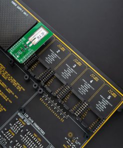
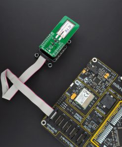
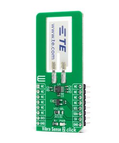
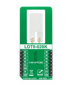
Vibra Sense 2 Click
R550.00 ex. VAT
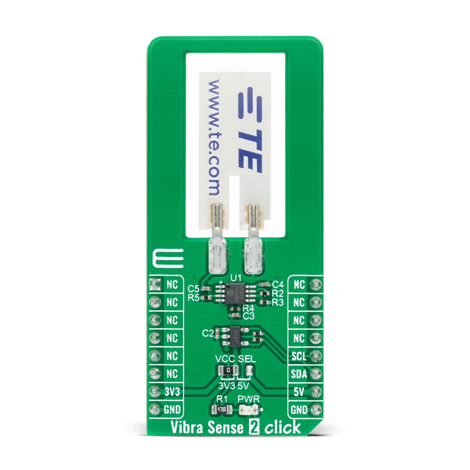
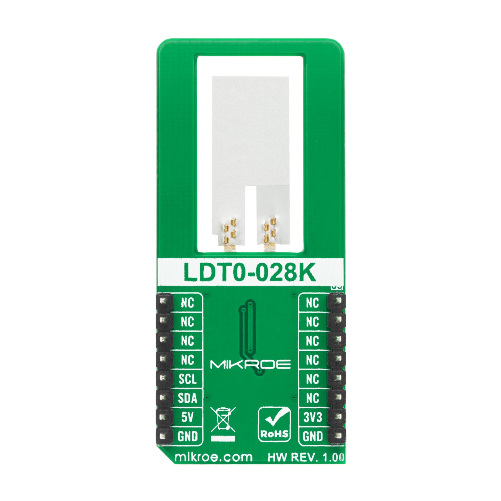
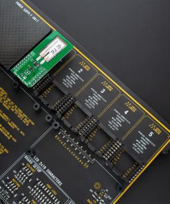
Vibra Sense 2 Click is a compact add-on board that contains a piezo sensor suitable for vibration measurements. This board features the LDT0-028K, a flexible 28 μm thick piezoelectric PVDF polymer film with screen-printed silver ink electrodes, laminated to a 0.125 mm polyester substrate, and fitted with two crimped contacts from TE Connectivity. The sensing element of the LDT0-028K comprises a cantilever beam loaded by an additional mass to offer high sensitivity at low frequencies. Some features of this Click board™ like flexibility, high sensitivity, and performance make it an excellent choice for vibrating sensing applications, security systems, body movement, and many more.
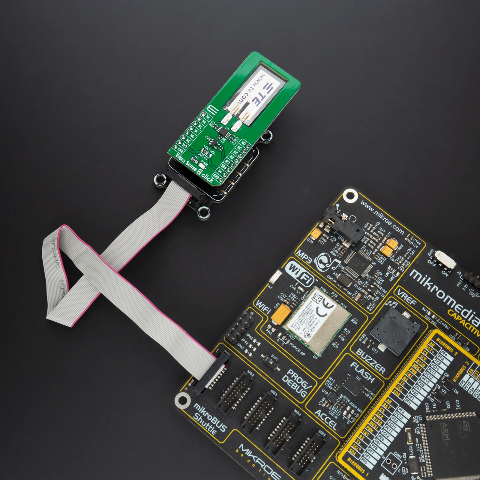
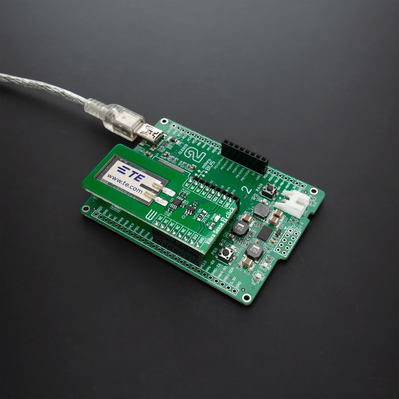
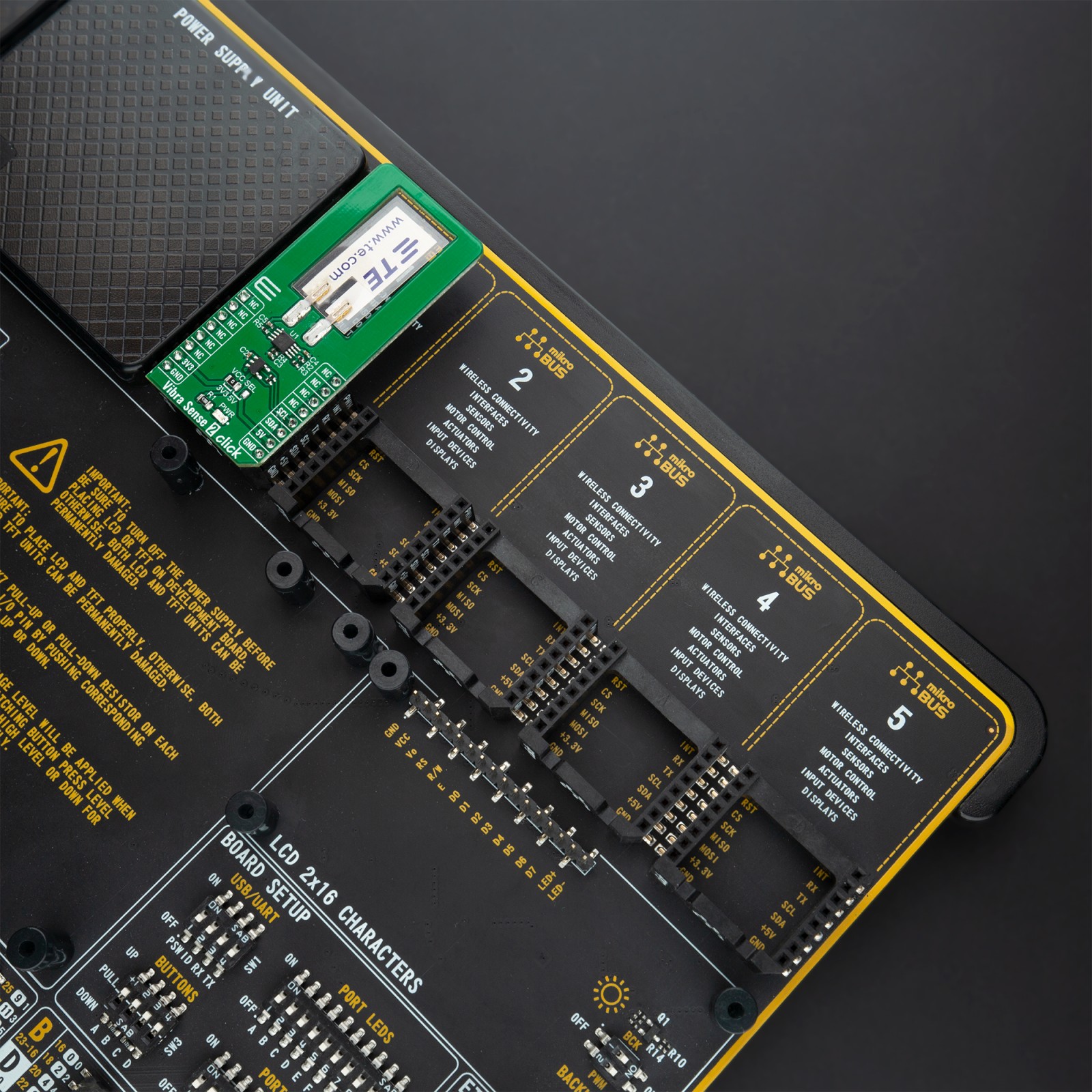
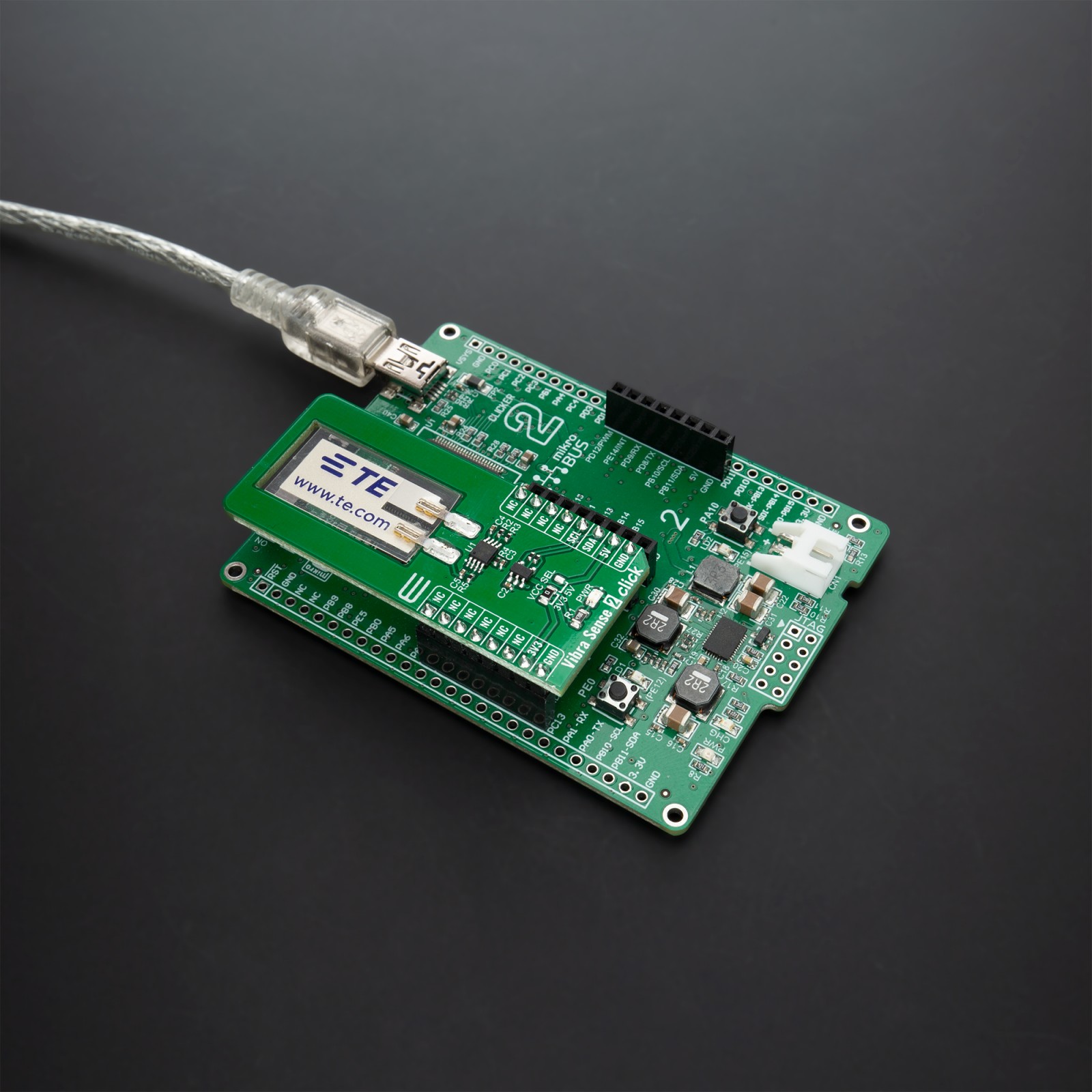
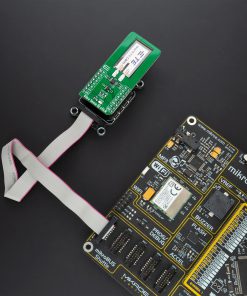
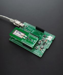
Vibra Sense 2 Click is supported by a mikroSDK compliant library, which includes functions that simplify software development. This Click board™ comes as a fully tested product, ready to be used on a system equipped with the mikroBUS™ socket.
Stock: Lead-time applicable.
| 5+ | R522.50 |
| 10+ | R495.00 |
| 15+ | R467.50 |
| 20+ | R449.90 |
How does it work?
Vibra Sense 2 Click is based on the LDT0-028K, a flexible 28 μm thick piezoelectric PVDF polymer film with screen-printed silver ink electrodes, laminated to a 0.125 mm polyester substrate, and fitted with two crimped contacts from TE Connectivity. This piezo sensor comes with solderable crimp pins often used for flex, touch, vibration, and shock measurements. When the sensor moves back and forth, a small AC and large voltage will be created by the voltage comparator inside of it. Although, it has a high receptivity for strong impacts with a wide dynamic range that also guarantees excellent measuring performance.

The LDTM-028K is a vibration sensor where the sensing element comprises a cantilever beam loaded by an additional mass to offer high sensitivity at low frequencies. A charge amplifier detects the output signal as vibration and sends it on the single-ended analog input pin of the ADC. Using a charge amplifier allows a very long measurement time constant and thus allows the “open-circuit” voltage response to be calculated). To bring the corresponding signal to the ADC pin, this Click board™ uses an analog circuitry made of OpAmp MCP6282 from Microchip that has a function of a buffer.
Vibra Sense 2 Click communicates with MCU through the MCP3221, a successive approximation A/D converter with a 12-bit resolution from Microchip, using a 2-wire I2C compatible interface. This device provides one single-ended input with very low-power consumption, a low maximum conversion current, and a Standby current of 250 μA and 1 μA, respectively. Data on the I2C bus can be transferred at rates of up to 100 kbit/s in the Standard Mode, and up to 400 kbit/s in the Fast Mode. Also, maximum sample rates of 22.3 kSPS with the MCP3221 are possible in a Continuous-Conversion Mode with a clock rate of 400 kHz.
This Click board™ is designed to be operated with both 3.3V and 5V logic voltage levels that can be selected via VCC SEL jumper. This allows for both 3.3V and 5V capable MCUs to use the I2C communication lines properly. However, the Click board™ comes equipped with a library that contains easy to use functions and an example code that can be used as a reference for further development.
Specifications
Type
Force
Applications
Can be used for vibrating sensing applications, security systems, body movement, and many more.
On-board modules
Vibra Sense 2 Click is based on the LDT0-028K, a flexible 28 μm thick piezoelectric PVDF polymer film with screen-printed silver ink electrodes, laminated to a 0.125 mm polyester substrate, and fitted with two crimped contacts from TE Connectivity.
Key Features
Low power consumption, high sensitivity, excellent measuring performance, high receptivity for strong impacts with a wide dynamic range, and more.
Interface
I2C
Feature
No ClickID
Compatibility
mikroBUS™
Click board size
L (57.15 x 25.4 mm)
Input Voltage
3.3V or 5V
Pinout diagram
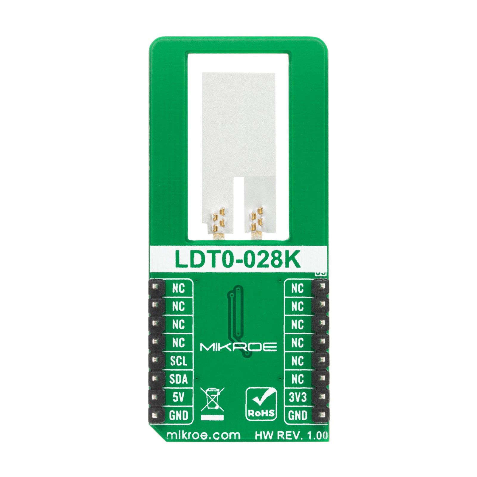
This table shows how the pinout on Vibra Sense 2 Click corresponds to the pinout on the mikroBUS™ socket (the latter shown in the two middle columns).
Onboard settings and indicators
| Label | Name | Default | Description |
|---|---|---|---|
| LD1 | PWR | – | Power LED Indicator |
Vibra Sense 2 Click electrical specifications
| Description | Min | Typ | Max | Unit |
|---|---|---|---|---|
| Supply Voltage | -0.3 | – | 6 | V |
| Sensing Range | 0 | – | 180 | Hz |
| Sensitivity | 50 | – | 800 | mV/g |
| Maximum Sample Rate | – | – | 22.3 | kSPS |
| Operating Temperature Range | 0 | – | +85 | °C |
Software Support
We provide a library for the Vibra Sense 2 Click on our LibStock page, as well as a demo application (example), developed using MikroElektronika compilers. The demo can run on all the main MikroElektronika development boards.
Library Description
The library covers all the necessary functions that enables the usage of the Vibra Sense 2 Click board™. It offers reading from output register, calculations that result in relatively accurate measurement of output voltage and the vibration level of the piezo element.
Key functions:
uint16_t vibrasense2_read_data ( );– Function is used to read raw data from MCP3221.uint16_t vibrasense2_read_voltage ( uint16_t v_ref );– Function is used to calculate piezo voltage in millivolts.int8_t vibrasense2_vibration_level ( );– Function is used to get vibration level.
Examples description
The application is composed of three sections :
- System Initialization – Initializes I2C module ans LOG structure.
- Application Initialization – Initalizes I2C driver and makes an initial log.
- Application Task – Demonstrates use of Vibra Sense 2 Click board™ by checking vibration levels and displaying changes via USART terminal.
void application_task ( )
{
    new_val = vibrasense2_vibration_level( );
    if ( new_val != old_val )
    {
        switch ( new_val )
        {
            case VIBRASENSE2_VIBRA_LVL_0:
            {
                mikrobus_logWrite( "No Vibration", _LOG_LINE );
                break;
            }
            case VIBRASENSE2_VIBRA_LVL_1:
            {
                mikrobus_logWrite( "Marginal Vibration", _LOG_LINE );
                break;
            }
            case VIBRASENSE2_VIBRA_LVL_2:
            {
                mikrobus_logWrite( "Slight Vibration", _LOG_LINE );
                break;
            }
            case VIBRASENSE2_VIBRA_LVL_3:
            {
                mikrobus_logWrite( "Enhanced Vibration", _LOG_LINE );
                break;
            }
            case VIBRASENSE2_VIBRA_LVL_4:
            {
                mikrobus_logWrite( "Moderate Vibration", _LOG_LINE );
                break;
            }
            case VIBRASENSE2_VIBRA_LVL_5:
            {
                mikrobus_logWrite( "High Vibration", _LOG_LINE );
                break;
            }
            case VIBRASENSE2_VIBRA_LVL_6:
            {
                mikrobus_logWrite( "Severe Vibration", _LOG_LINE );
                break;
            }
            default:
            {
                mikrobus_logWrite( "Error occured!", _LOG_LINE );
            }
        }
        old_val = new_val;
    }
}
The full application code, and ready to use projects can be found on our LibStock page.
Other mikroE Libraries used in the example:
- I2C
- UART
Additional notes and informations
Depending on the development board you are using, you may need USB UART click, USB UART 2 click or RS232 click to connect to your PC, for development systems with no UART to USB interface available on the board. The terminal available in all MikroElektronika compilers, or any other terminal application of your choice, can be used to read the message.
mikroSDK
This Click board™ is supported with mikroSDK – MikroElektronika Software Development Kit. To ensure proper operation of mikroSDK compliant Click board™ demo applications, mikroSDK should be downloaded from the LibStock and installed for the compiler you are using.
For more information about mikroSDK, visit the official page.
Resources
Downloads
| Weight | 28 g |
|---|---|
| Brand | MikroElektronika |

