-
×
 WiFi Plus Click
2 × R2,200.00
WiFi Plus Click
2 × R2,200.00 -
×
 M-BUS RF click
1 × R960.00
M-BUS RF click
1 × R960.00 -
×
 BEE Click
1 × R780.00
BEE Click
1 × R780.00 -
×
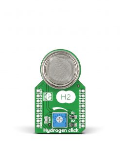 HYDROGEN Click
2 × R325.00
HYDROGEN Click
2 × R325.00 -
×
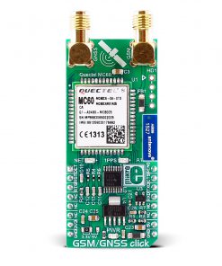 GSM/GNSS Click
1 × R1,650.00
GSM/GNSS Click
1 × R1,650.00 -
×
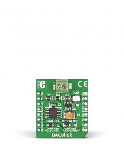 DAC Click
1 × R400.00
DAC Click
1 × R400.00 -
×
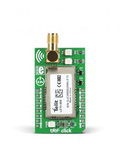 tRF Click
1 × R1,050.00
tRF Click
1 × R1,050.00 -
×
 IR Click
1 × R120.00
IR Click
1 × R120.00
Subtotal: R10,010.00