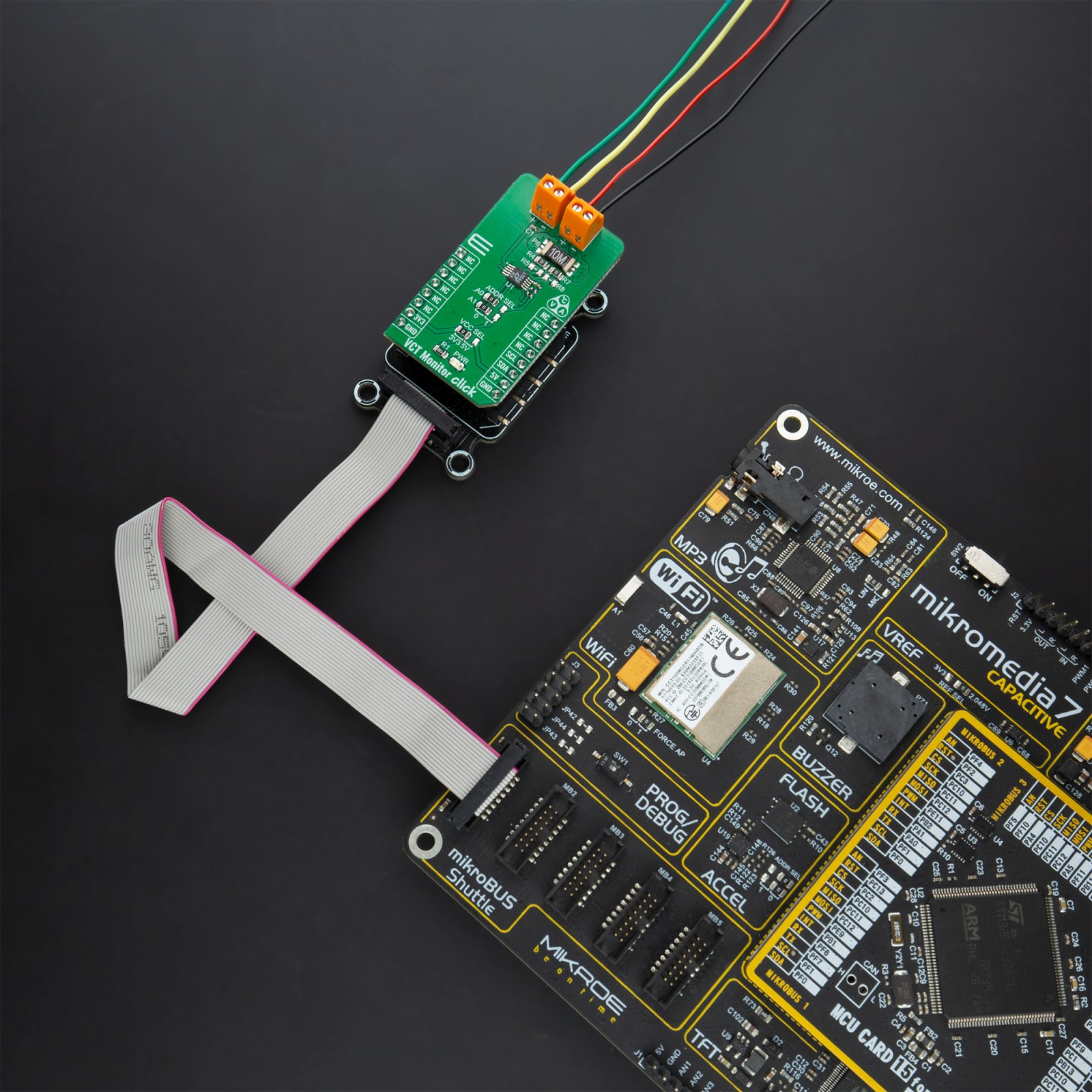
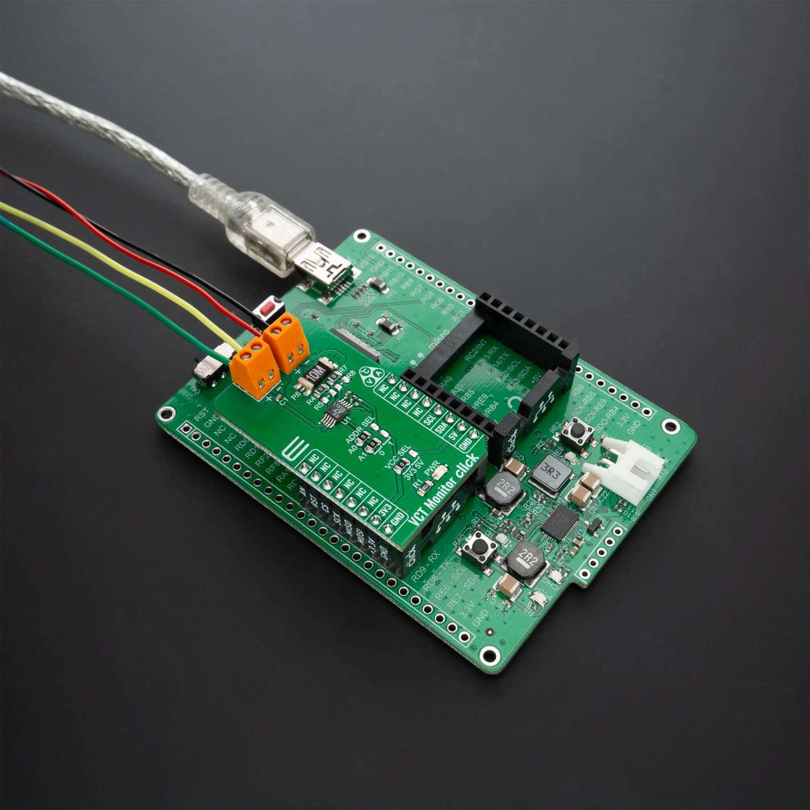
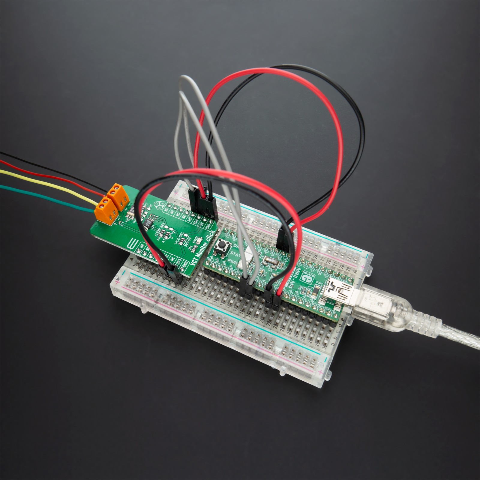
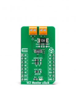
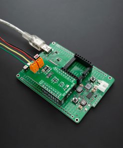
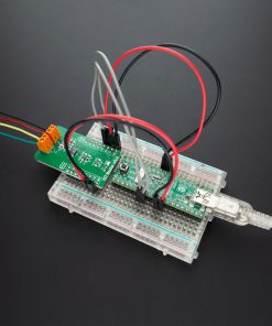
How does it work?
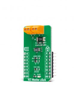
VCT Monitor Click is based on the LTC2990, a high-performance temperature, voltage, and current monitor with the I2C serial interface from Analog Devices. The LTC2990 can be configured to measure many combinations of internal temperature, remote temperature, remote voltage or current, and internal VCC with single or repeated measurements. It fits in systems needing sub-millivolt voltage resolution, 1% current measurement, and 1°C temperature accuracy or any combination of the three.
The input signals are selected with an input MUX, controlled by the control logic block. The control logic uses the mode bits in the control register to manage the sequence and types of data acquisition. The control logic also controls the variable current sources during remote temperature acquisition. The ADC performs the necessary conversion(s) and supplies the data to the control logic for further processing in the case of temperature measurements or routing to the appropriate data register for voltage and current measurements.
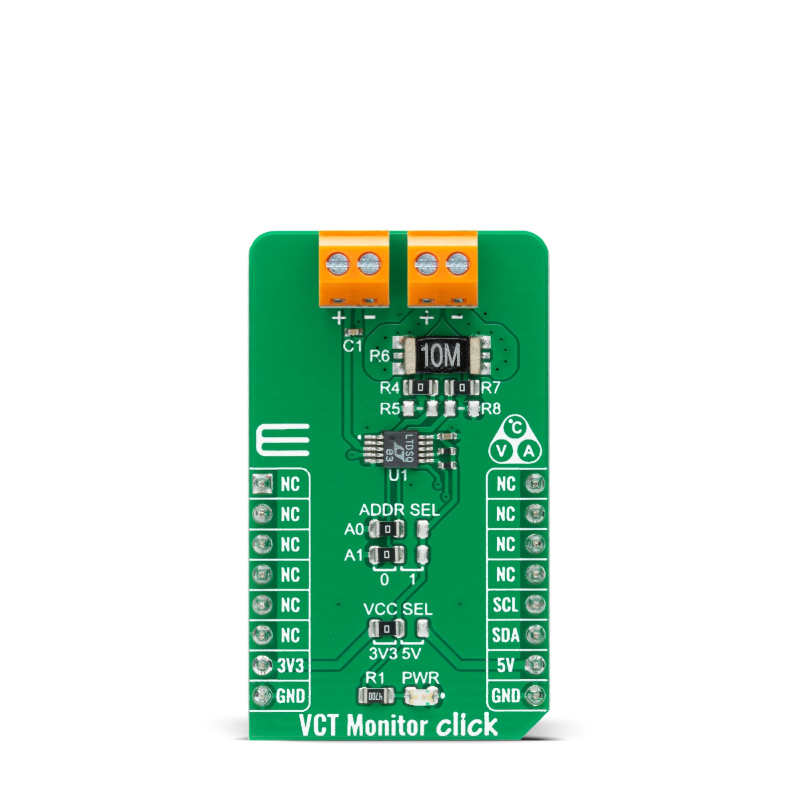
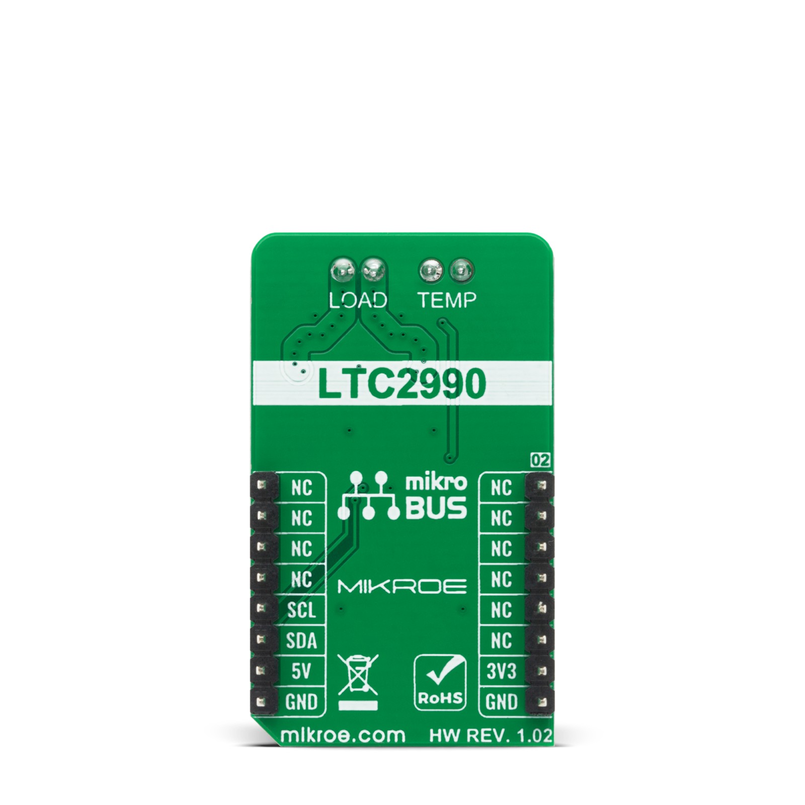
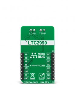
Remote measurements are performed on terminals labeled as TEMP and LOAD using multiple ADC conversions and source currents to compensate for sensor series resistance. The LTC2990 is calibrated to yield the correct temperature for a remote diode with an ideality factor of 1.004.
This Click board™ is designed to be operated with both 3.3V and 5V logic voltage levels that can be selected via VCC SEL jumper. This allows for both 3.3V and 5V capable MCUs to use the I2C communication lines properly. However, the Click board™ comes equipped with a library that contains easy to use functions and an example code that can be used as a reference for further development.
Specifications
Type
Current sensor,Measurements
Applications
Can be used for applications like supply voltage monitoring and remote diode temperature measurement, e.g., in industrial systems where thermal management is crucial for maximizing performance.
On-board modules
VCT Monitor Click is based on the LTC2990, a high-performance temperature, voltage, and current monitor with the I2C serial interface from Analog Devices.
Key Features
Low power consumption, high precission
Interface
I2C
Feature
No ClickID
Compatibility
mikroBUS™
Click board size
M (42.9 x 25.4 mm)
Input Voltage
3.3V or 5V
Pinout diagram
This table shows how the pinout on VCT Monitor Click corresponds to the pinout on the mikroBUS™ socket (the latter shown in the two middle columns).
Onboard settings and indicators
Label | Name | Default | Description |
---|---|---|---|
LD1 | PWR | – | Power LED Indicator |
JP1 | VCC SEL | Left | Power Supply Voltage Selection 3V3/5V: Left position 3V3, Right position 5V |
JP2-JP3 | ADDR SEL | Left | I2C Address Selection: Left position 0, Right position 1 |
VCT Monitor Click electrical specifications
Description | Min | Typ | Max | Unit |
---|---|---|---|---|
Supply Voltage | -0.3 | – | 6 | V |
Accuracy (Local) | – | – | ±3.5 | °C |
Accuracy (Remote) | – | – | ±1.5 | °C |
Resolution | – | 14 | – | bits |
Operating Temperature Range | 0 | – | 70 | °C |
Software Support
We provide a library for the VCT Monitor Click on our LibStock page, as well as a demo application (example), developed using MikroElektronika compilers. The demo can run on all the main MikroElektronika development boards.
Library Description
The library contains a basic functions for using VCT monitor click.
Key functions:
float vctmonitor_read_voltage_differential ( void )
– Differential voltage functionfloat vctmonitor_read_current ( void )
– Current functionfloat vctmonitor_read_temperature ( void )
– Temperature function
Examples description
The application is composed of three sections :
- System Initialization – Initializes I2C module
- Application Initialization – Initializes driver init
- Application Task – Reads temperature, current value, and differential voltage every 4 seconds.
- note – We used the next sets for the test: – Power supply – 4V – Current (Load) – 0A to 3A – The temperature reads from the external MMBT3904 sensor
void application_task ( ) { float temperature; float voltage; float current; current = vctmonitor_read_current( ); FloatToStr( current,demo_text ); mikrobus_logWrite( "Current: ",_LOG_TEXT ); mikrobus_logWrite( demo_text,_LOG_TEXT ); mikrobus_logWrite( "mA",_LOG_LINE ); voltage = vctmonitor_read_voltage_differential( ); FloatToStr( voltage,demo_text ); mikrobus_logWrite( "Voltage: ",_LOG_TEXT ); mikrobus_logWrite( demo_text,_LOG_TEXT ); mikrobus_logWrite( "mV",_LOG_LINE ); temperature = vctmonitor_read_temperature(); FloatToStr( temperature, demo_text ); mikrobus_logWrite( "Temperature: ", _LOG_TEXT ); mikrobus_logWrite( demo_text, _LOG_TEXT); mikrobus_logWrite( "C",_LOG_LINE ); mikrobus_logWrite("_________________",_LOG_LINE); Delay_ms( 4000 ); }
The full application code, and ready to use projects can be found on our LibStock page.
Other mikroE Libraries used in the example:
- I2C Library
- Conversions Library
- UART Library
Additional notes and informations
Depending on the development board you are using, you may need USB UART click, USB UART 2 click or RS232 click to connect to your PC, for development systems with no UART to USB interface available on the board. The terminal available in all MikroElektronika compilers, or any other terminal application of your choice, can be used to read the message.
mikroSDK
This Click board™ is supported with mikroSDK – MikroElektronika Software Development Kit. To ensure proper operation of mikroSDK compliant Click board™ demo applications, mikroSDK should be downloaded from the LibStock and installed for the compiler you are using.
For more information about mikroSDK, visit the official page.