How does it work?
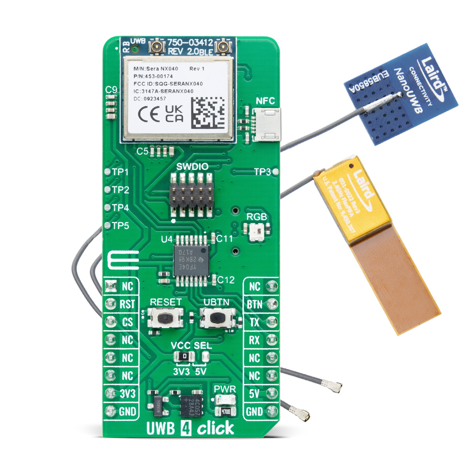
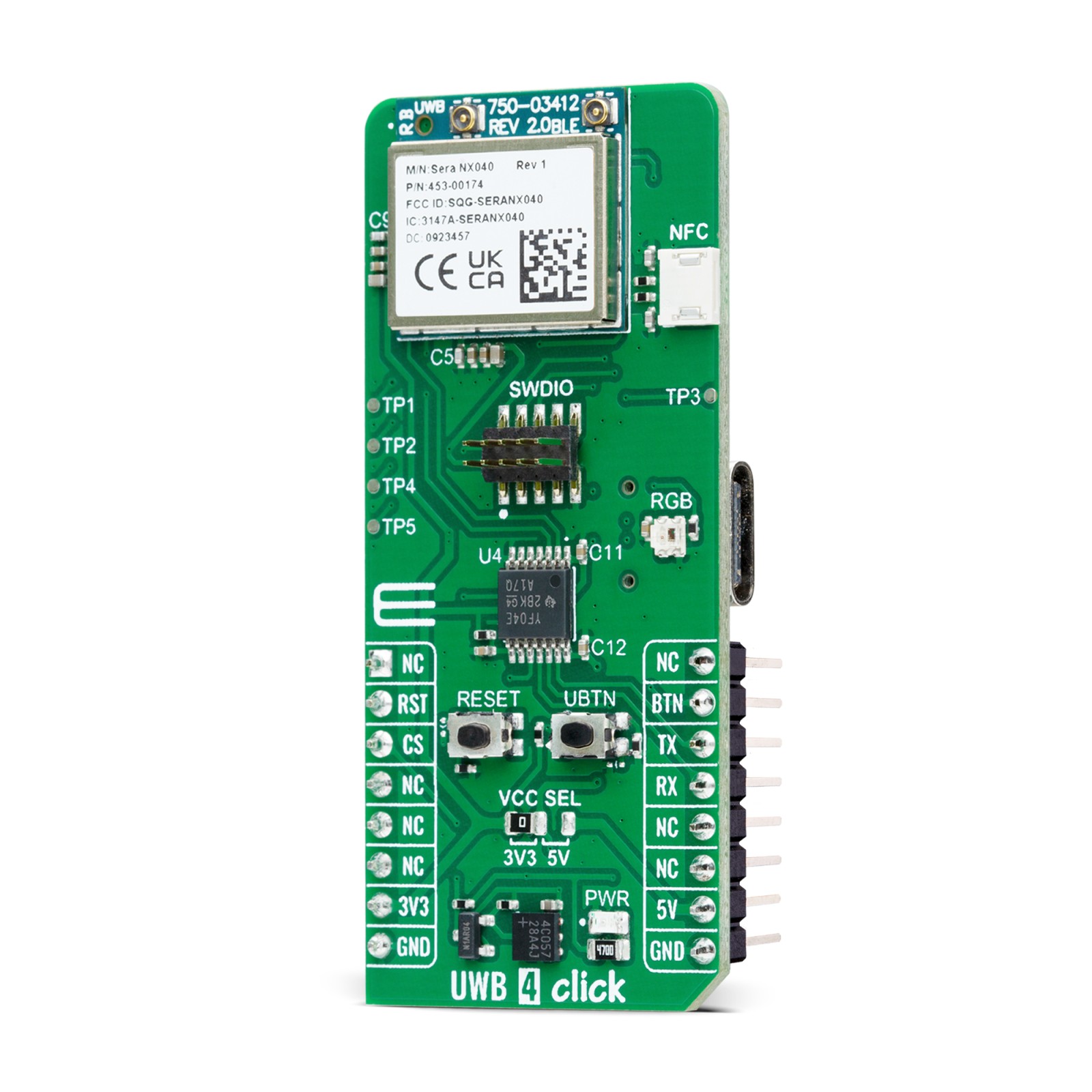
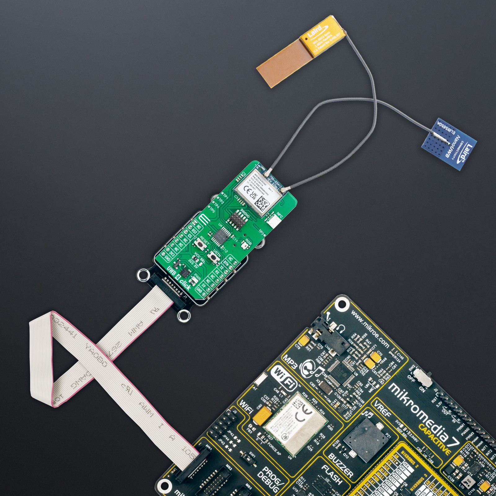
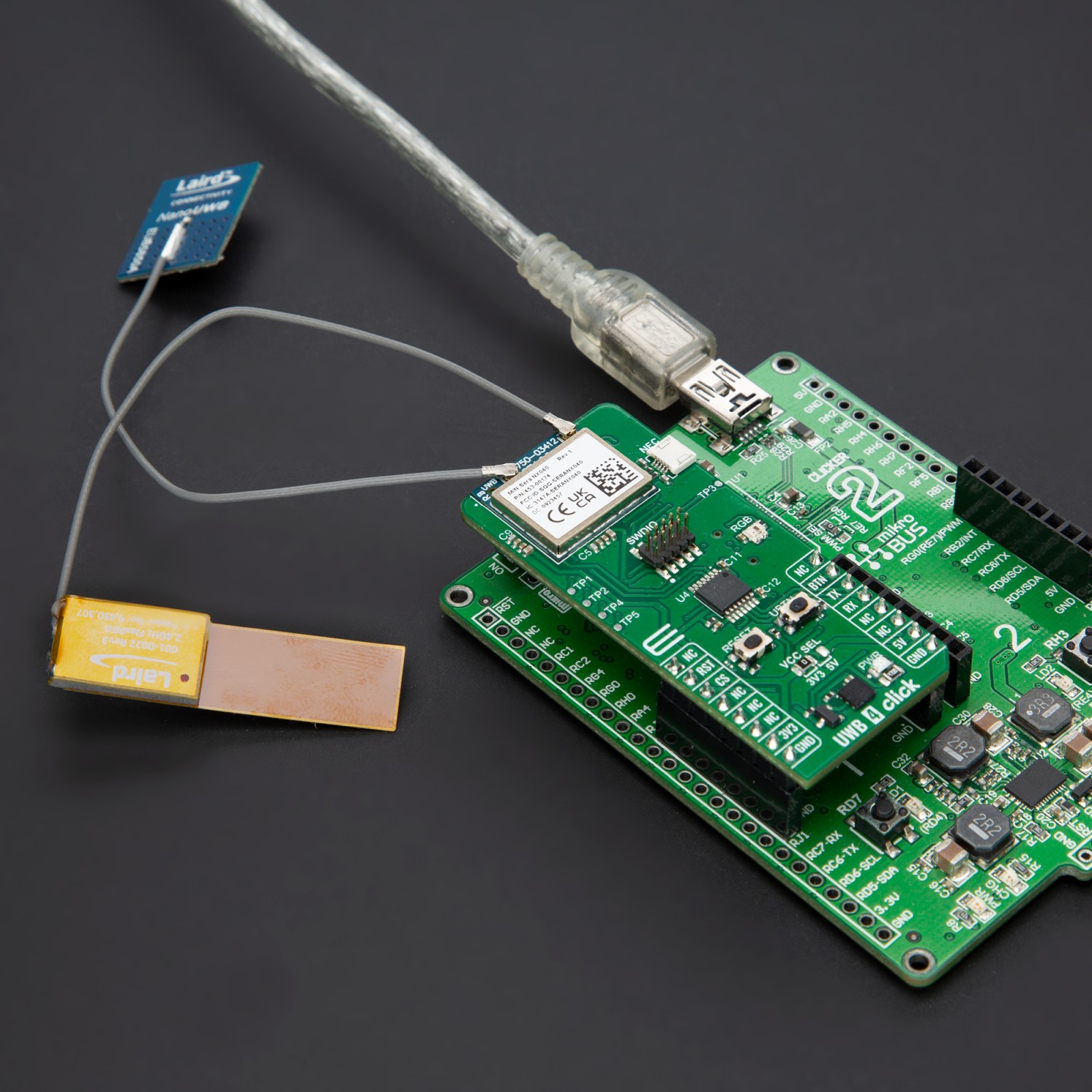
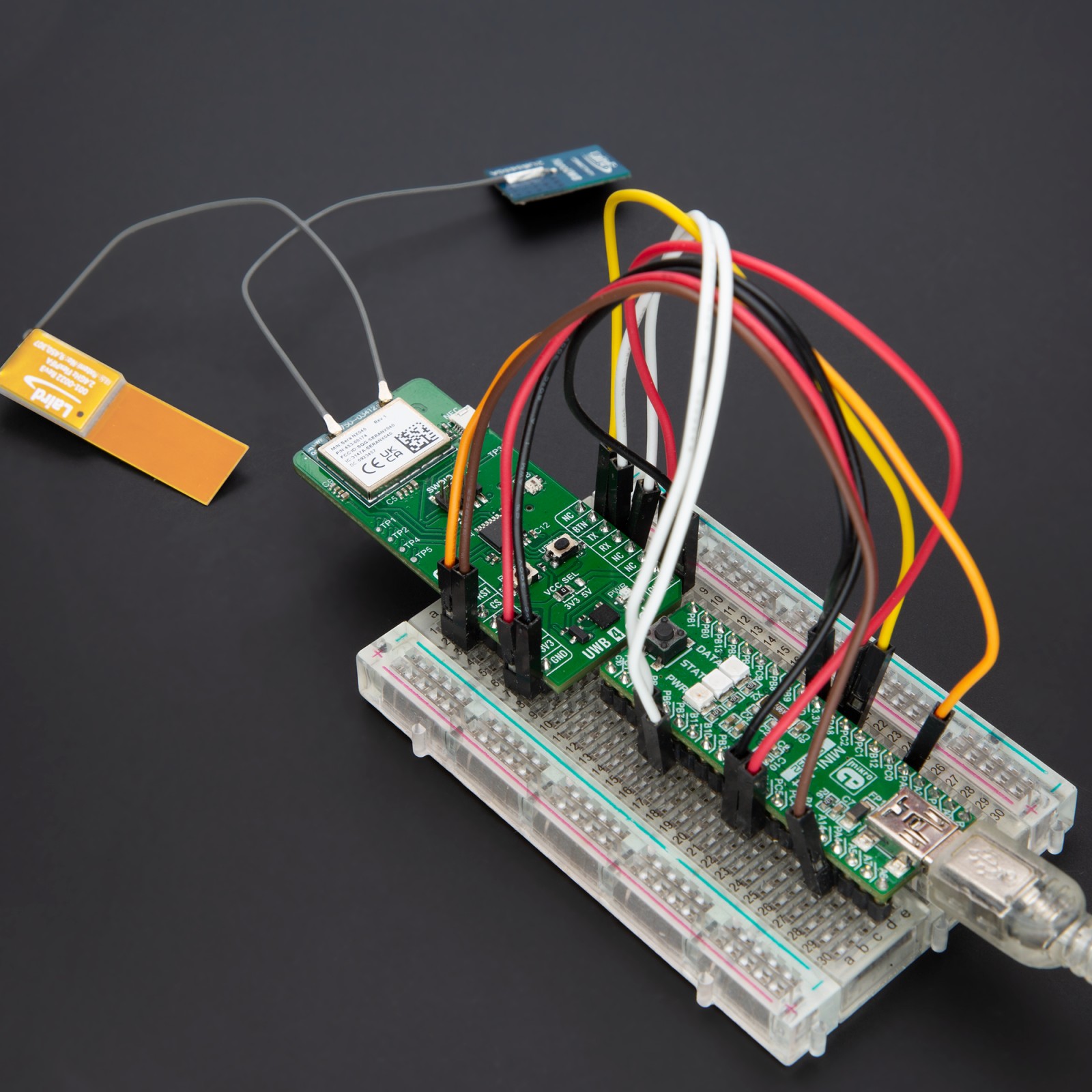
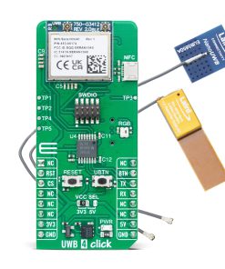
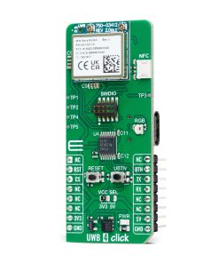
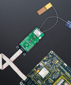
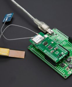
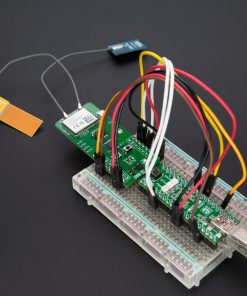
UWB 4 Click is based on the Sera NX040 (453-00174C), an advanced UWB/BLE module equipped with external antenna connectors from Ezurio. The module features top-tier silicon: NXP’s SR040 chipset for ultra-wideband (UWB) and Nordic Semiconductor’s nRF52833 for Bluetooth LE, providing outstanding performance in precise positioning and wireless communication. Moreover, the module is pre-calibrated for regulatory compliance and optimized for superior ranging performance across various temperatures and UWB antenna implementations, making this Click board™ ideal for precise indoor positioning and location-based applications, such as asset tracking, navigation, and industrial automation.
As mentioned, at the heart of the Sera NX040 is the NXP SR040 Ultra-Wideband Transceiver, which supports IEEE 802.15.4/4z High Precision Ranging (HPR) UWB operations. It includes a fully embedded FiRa-compliant MAC and PHY, allowing for seamless Two-Way Ranging (TWR) sessions in both initiator and responder modes, as well as Blink mode operation within Time Difference of Arrival (TDoA) systems. The SR040 achieves exceptional ranging accuracy of less than ±10cm, with a typical receiver sensitivity of -92dBm. Additionally, the module incorporates the Nordic Semiconductor nRF52833 chipset, a fully certified Bluetooth SoC that supports Bluetooth (LE) 5.4 for the efficient provisioning, setup, and control of UWB ranging sessions. The nRF52833 offers a maximum transmit output power of +8dBm and a typical receive sensitivity of -96dBm.
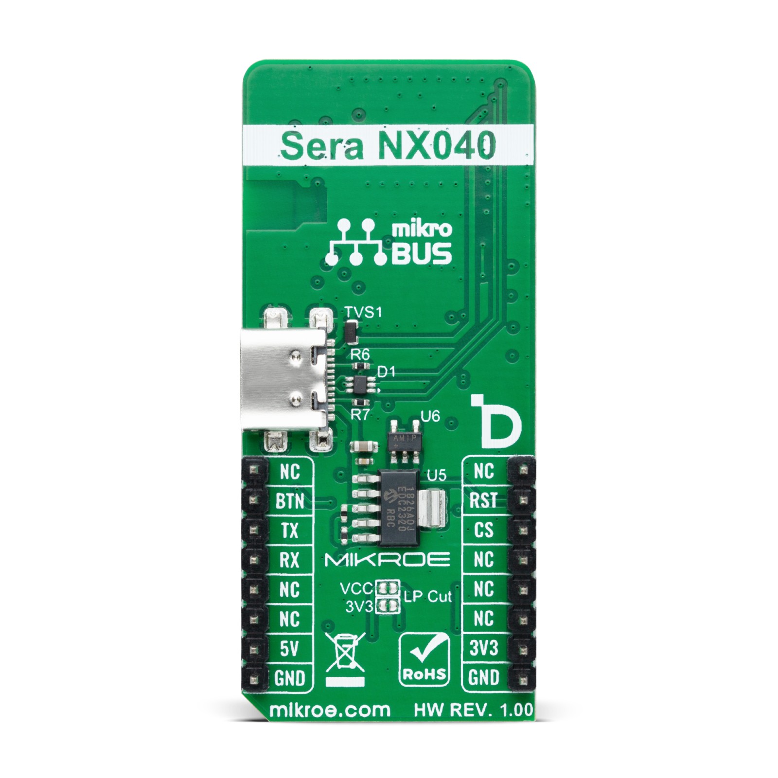
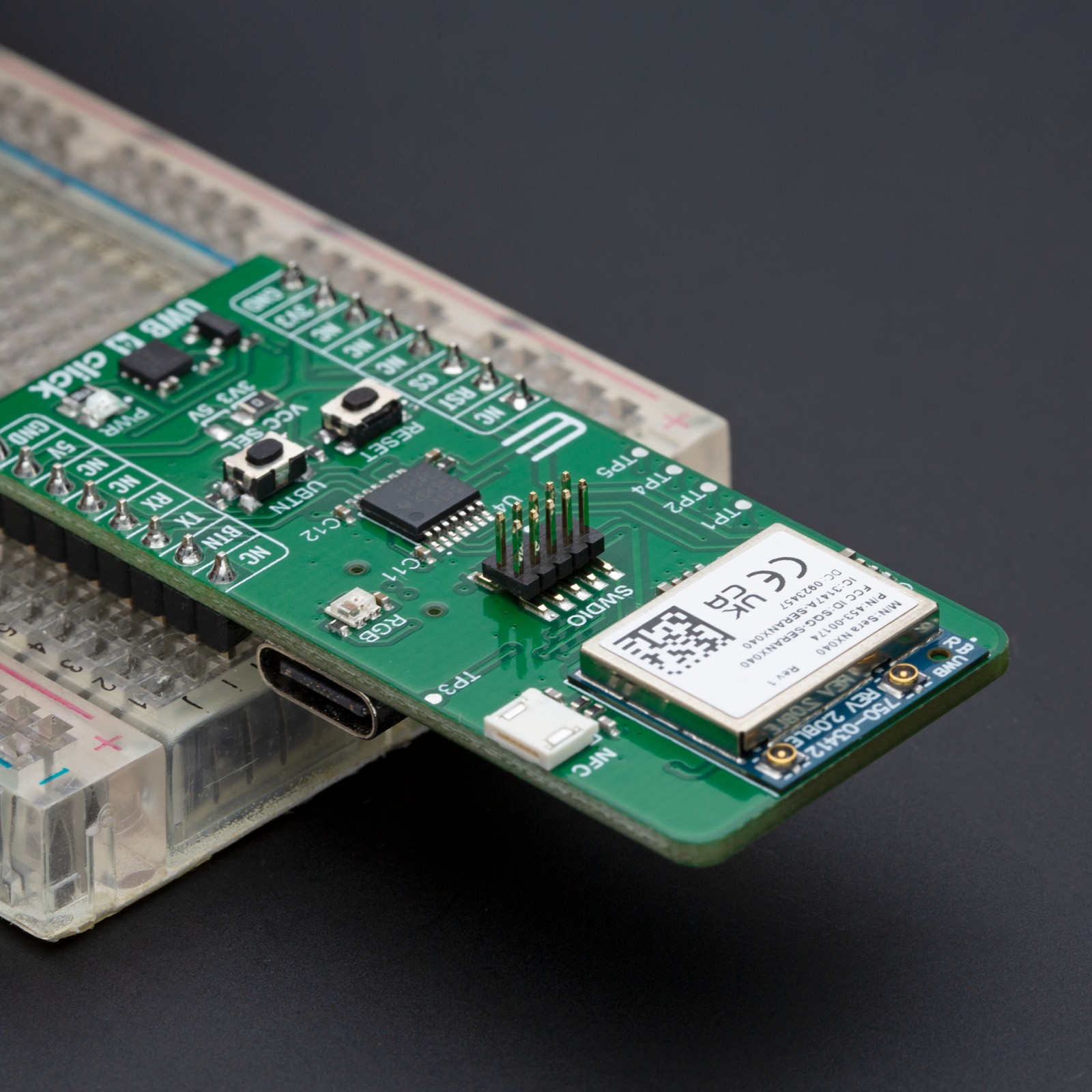
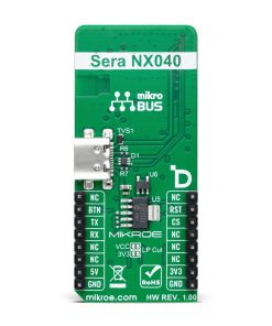
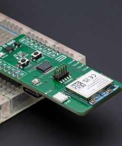
The Sera NX040 achieves communication with the host MCU via a UART interface via standard RX and TX pins. With a default baud rate of 115200bps, this setup ensures efficient and reliable data transfer. In addition to UART, this board is equipped with a USB type-C connector for USB 2.0 FS (Full Speed, 12Mbps), enabling direct connection to the Sera NX040 module’s USB port for flexible integration. When using the USB interface, the entire system is powered by a 3.3V supply provided by the MCP1826 LDO regulator, which converts the 5V from the USB to 3.3V.
For development and debugging, the module provides a SWDIO header that grants access to the nRF52833’s SWD (JTAG) interface, making it compatible with the Nordic SDK. This interface is crucial for developers leveraging advanced features and performing in-depth testing. Comprehensive support for USB drivers is available through the Nordic SDK, enhancing the module’s versatility in various development environments.
NOTE: For detailed information on software, documentation, and the latest updates, please visit the official Sera NX040 product page and its GitHub repository.
In addition to the interface pins, this Click board™ features a reset pin (RST) and a RESET button for module resetting. It also includes a user pin (BTN) and button (UBTN) for interactive control over the program flow. An RGB LED acts as a user-configurable red LED indicator, providing visual feedback for various statuses, such as UART messaging, boot processes, or debugger commands. The board also includes an NFC antenna connector for NFC applications and test points for debugging and monitoring. TP1 and TP2 serve as the second UART pins of the Sera NX040, while TP3, TP4, and TP5 provide access to the SR040 RST, SWCLK, and SWDIO pins, respectively. These features enable easy access to testing and development, making the board highly versatile for a wide range of applications.
At the bottom of the UWB 4 Click, there are LP Cut traces. By cutting these traces, you can achieve low power consumption by disconnecting the PWR LED and ClickID from the circuit, resulting in additional power savings.
This Click board™ can operate with both 3.3V and 5V logic voltage levels selected via the VCC SEL jumper. Given that the Sera NX040 module operates at 3.3V, a logic-level translator, the TXS0104, is also used for proper operation and an accurate signal-level translation. This way, both 3.3V and 5V capable MCUs can use the communication lines properly. Also, this Click board™ comes equipped with a library containing easy-to-use functions and an example code that can be used as a reference for further development.
Specifications
Type
UWB
Applications
Ideal for asset tracking, navigation, and industrial automation applications
On-board modules
Sera NX040 (453-00174C) – UWB/BLE module from Ezurio
Key Features
Ultra-Wideband (UWB) technology, Bluetooth LE connectivity, UART and USB interfaces, SWDIO, equipment for user interactions (buttons, LED, and test points), low-power mode, two Ezurio antennas included in the package, and more
Interface
UART,USB
Feature
ClickID
Compatibility
mikroBUS™
Click board size
L (57.15 x 25.4 mm)
Input Voltage
3.3V or 5V
Pinout diagram
This table shows how the pinout on UWB 4 Click corresponds to the pinout on the mikroBUS™ socket (the latter shown in the two middle columns).
Onboard settings and indicators
Label | Name | Default | Description |
---|---|---|---|
LD1 | PWR | – | Power LED Indicator |
LD2 | RGB | – | User-Configurable LED Indicator |
JP1 | VCC SEL | Left | Power Voltage Level Selection 3V3/5V: Left position 3V3, Right position 5V |
NT1-NT2 | LP Cut | Connected | Low Power Mode Traces |
T1 | RESET | – | Reset Button |
T2 | UBTN | – | User Interaction Button |
TP1-TP2 | TP1-TP2 | – | UART1 Interface Test Points |
TP3-TP5 | TP1-TP2 | – | SR040 RST/SWCLK/SWDIO Test Points |
UWB 4 Click electrical specifications
Description | Min | Typ | Max | Unit |
---|---|---|---|---|
Supply Voltage | 3.3 | – | 5 | V |
UWB Frequency Range | 6.24 | – | 8.24 | GHz |
UWB Channel Bandwidth | – | 500 | – | MHz |
UWB RX Sensitivity | – | -92 | – | dBm |
UWB Ranging ToF Accuracy | -10 | – | +10 | cm |
BLE Frequency Range | 2402 | – | 2480 | MHz |
BLE RX Sensitivity | – | -96 | – | dBm |
Software Support
We provide a library for the UWB 4 Click as well as a demo application (example), developed using MIKROE compilers. The demo can run on all the main MIKROE development boards.
Package can be downloaded/installed directly from NECTO Studio Package Manager (recommended), downloaded from our LibStock™ or found on MIKROE github account.
Library Description
This library contains API for UWB 4 Click driver.
Key functions
-
uwb4_cmd_run
This function sends a specified command to the click module. -
uwb4_cmd_set
This function sets a value to a specified command of the click module. -
uwb4_reset_device
This function resets the device by toggling the reset pin logic state.
Example Description
This example demonstrates the use of UWB 4 Click board™ by showing the UWB ranging between two click boards configured as initiator and responder.
void application_task ( void )
{
switch ( app_state )
{
case UWB4_POWER_UP:
{
if ( UWB4_OK == uwb4_power_up( &uwb4 ) )
{
app_state = UWB4_CONFIG_EXAMPLE;
log_printf( &logger, ">>> APP STATE - CONFIG EXAMPLE <<<rnn" );
}
break;
}
case UWB4_CONFIG_EXAMPLE:
{
if ( UWB4_OK == uwb4_config_example( &uwb4 ) )
{
app_state = UWB4_EXAMPLE;
log_printf( &logger, ">>> APP STATE - EXAMPLE <<<rnn" );
}
break;
}
case UWB4_EXAMPLE:
{
uwb4_example( &uwb4 );
break;
}
default:
{
log_error( &logger, " APP STATE." );
break;
}
}
}
The full application code, and ready to use projects can be installed directly from NECTO Studio Package Manager (recommended), downloaded from our LibStock™ or found on MIKROE github account.
Other MIKROE Libraries used in the example:
- MikroSDK.Board
- MikroSDK.Log
- Click.UWB4
Additional notes and informations
Depending on the development board you are using, you may need USB UART click, USB UART 2 Click or RS232 Click to connect to your PC, for development systems with no UART to USB interface available on the board. UART terminal is available in all MIKROE compilers.
mikroSDK
This Click board™ is supported with mikroSDK – MIKROE Software Development Kit. To ensure proper operation of mikroSDK compliant Click board™ demo applications, mikroSDK should be downloaded from the LibStock and installed for the compiler you are using.
For more information about mikroSDK, visit the official page.