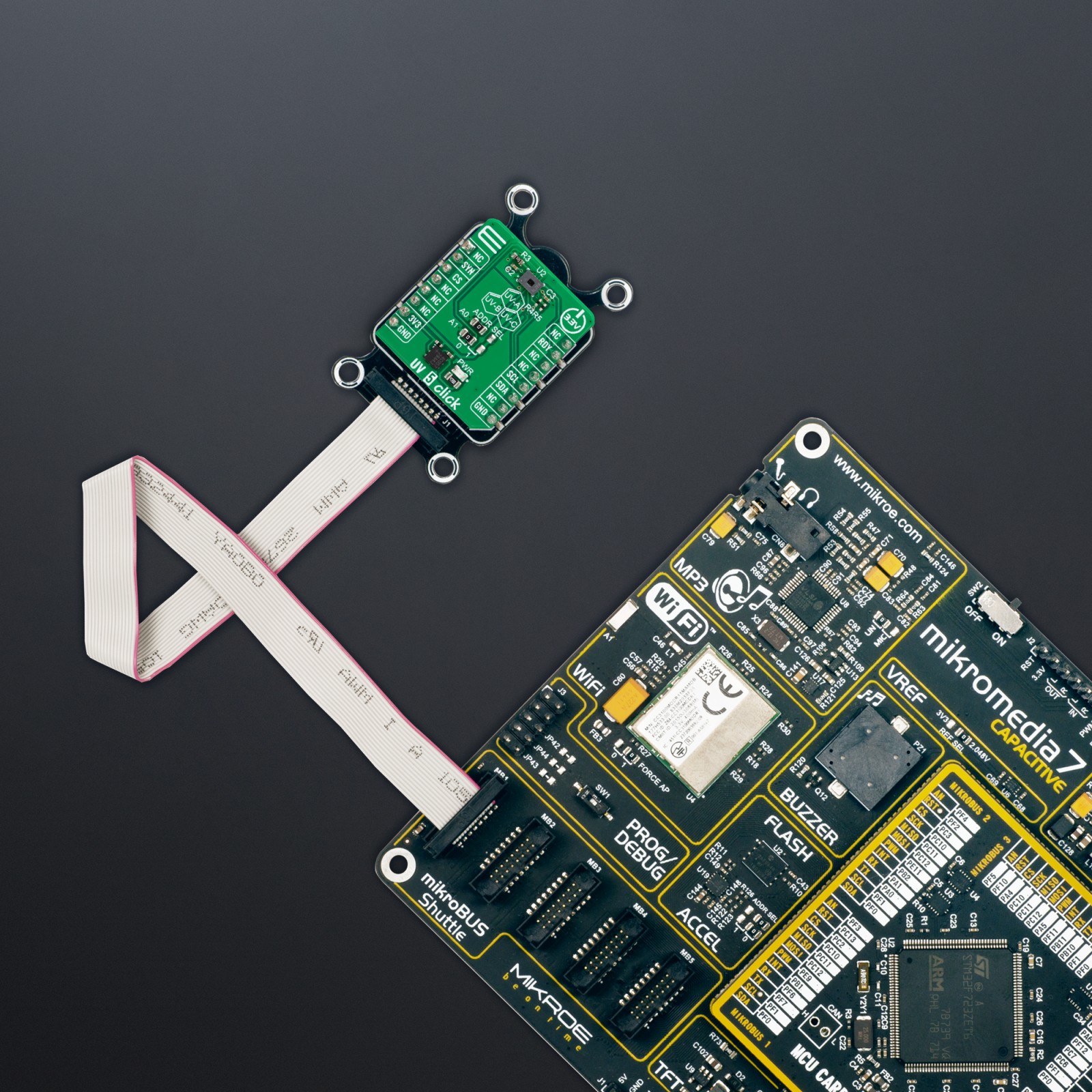
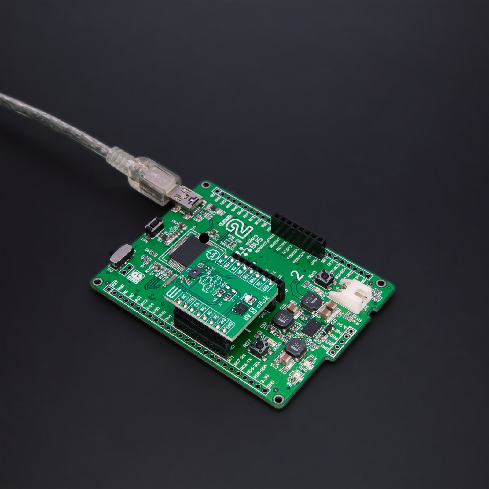
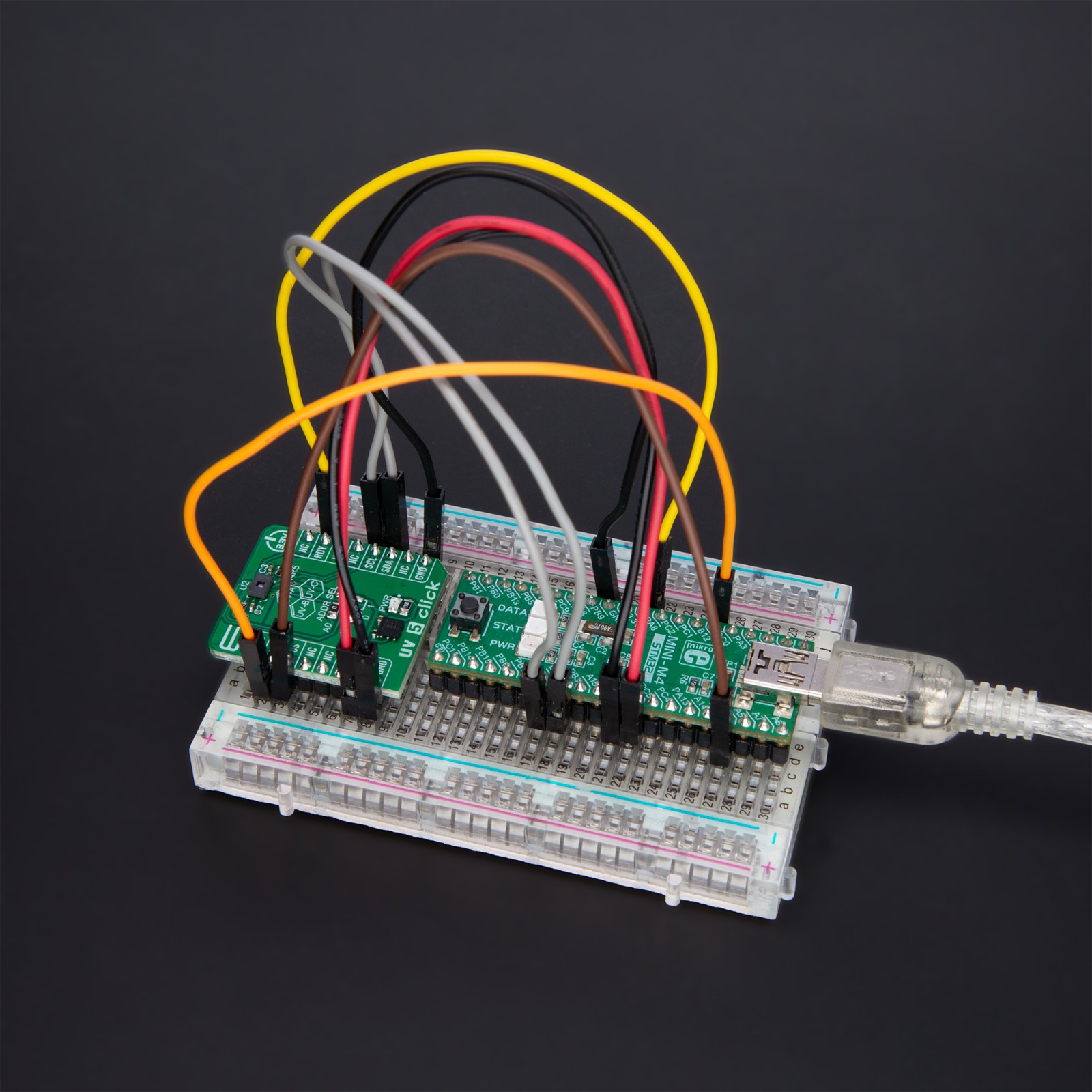
How does it work?
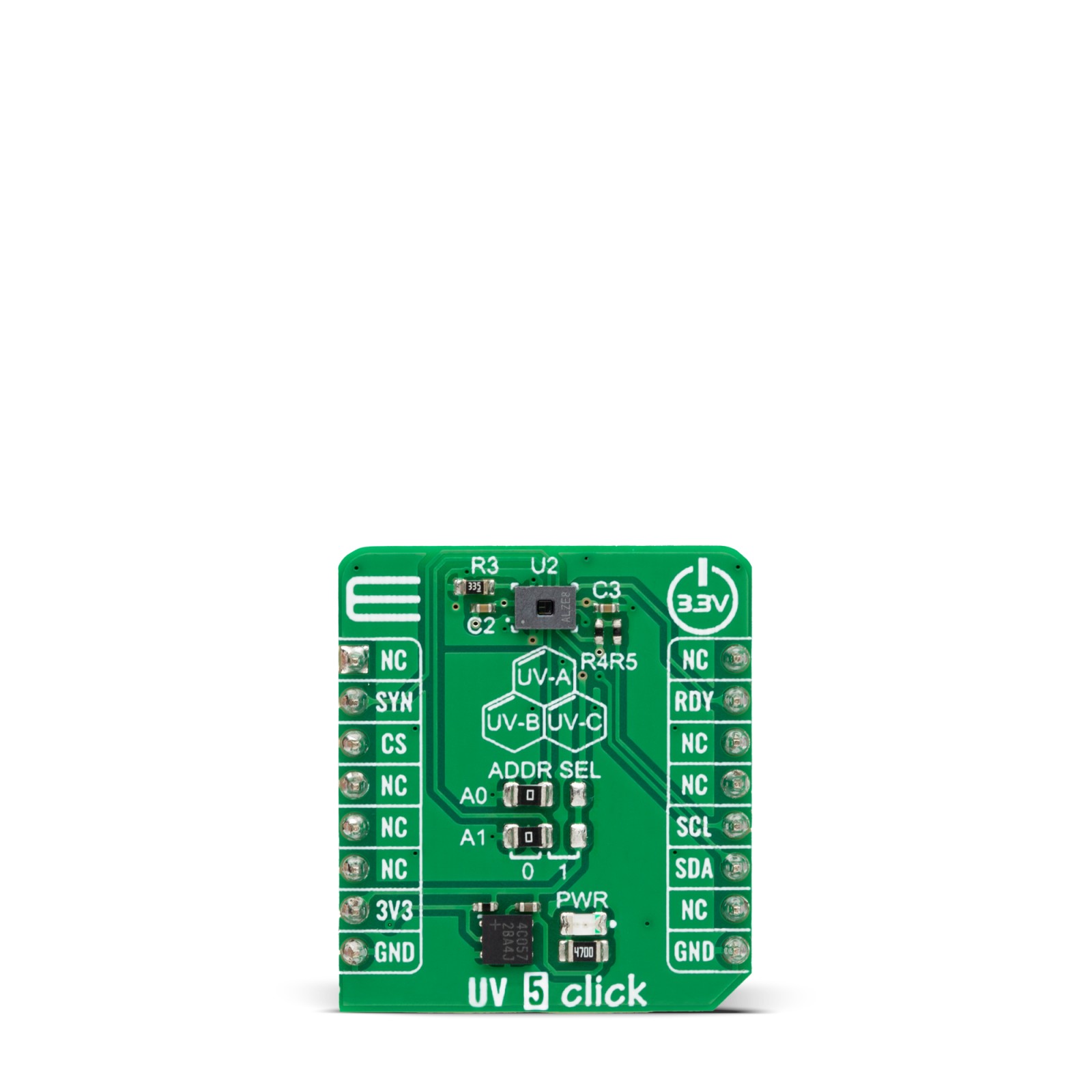
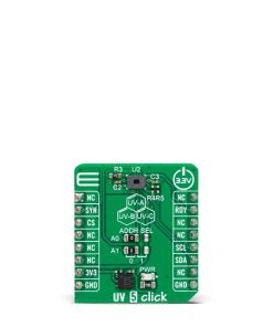
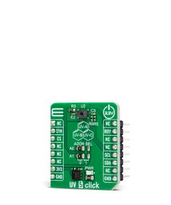
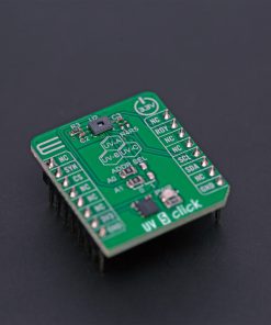
UV 5 Click is based on the AS7331, a spectral UVA/B/C sensor from ams OSRAM. It converts optical radiation signals to a digital result by three photodiodes of three separated UVA, UVB, and UVC channels. This way, the sensor realizes a continuous or triggered measurement. You can adjust irradiance responsivity via gain, conversion time, and internal clock frequency to affect sensitivity, full-scale range, and LSB. The gain comes in a range of 12 steps divided by a factor of two for each step, while the conversion time is internally controlled over a range of 15 steps, again by a factor of two for each step.
The AS7331 sensor operates in two different states. Configuration state enables access to the configuration settings when a measurement is impossible. Measurement state has several modes: continuous measurement mode, command measurement mode, synchronous measurement mode, and synchronous measurement start and end mode. You define the measurement mode that the sensor over the software will perform. In addition, the sensor has power-saving options, such as power down and standby.
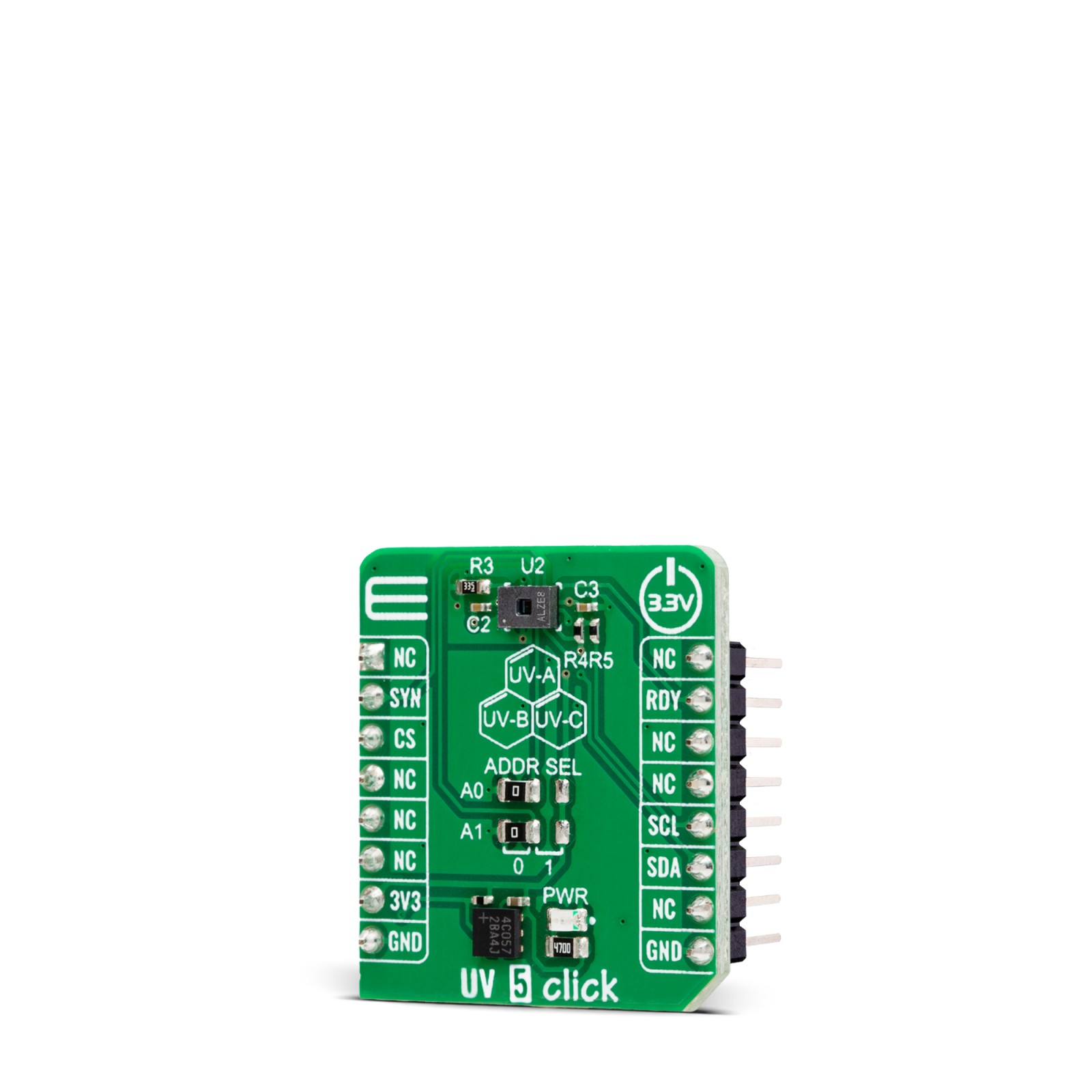
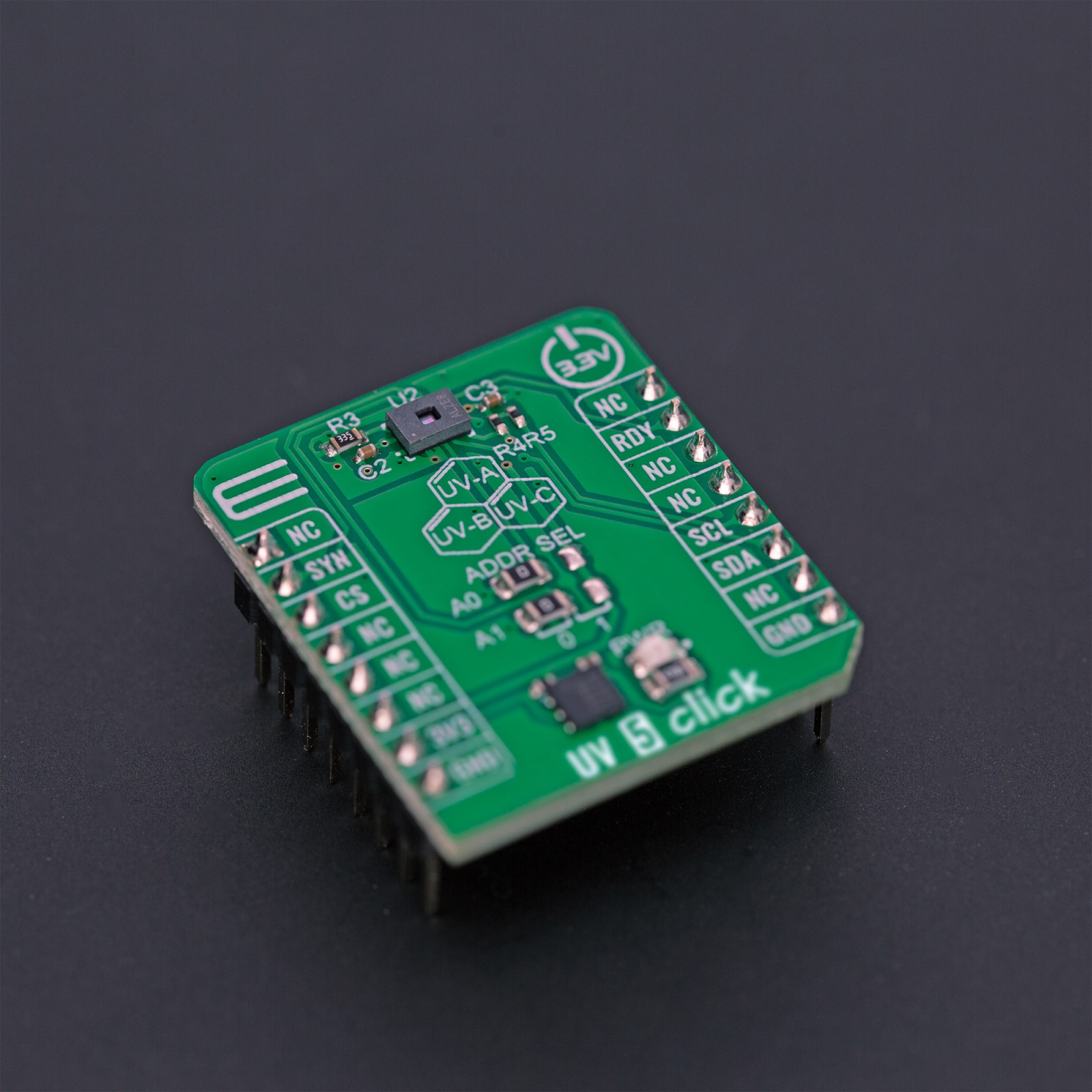
UV 5 Click uses a standard 2-Wire I2C interface to communicate with the host MCU, supporting a bit rate of up to 400kbit/s. Select an I2C address over two ADDR SEL jumpers (0 is set by default). For externally triggered start or start and stop of the measurement, you can synchronize the SYNC input of the AS7331, which is an externally controlled conversion input. The sensor will notify the end of each conversion over the RDY pin.
This Click board™ can be operated only with a 3.3V logic voltage level. The board must perform appropriate logic voltage level conversion before using MCUs with different logic levels. Also, it comes equipped with a library containing functions and an example code that can be used as a reference for further development.
Specifications
Type
Optical
Applications
Can be used for the development of applications for UV disinfection, UV-curving, partial discharge monitoring, analytics (water monitoring, microorganism contaminations), phototherapy, skin diagnostics, horticulture, and more
On-board modules
AS7331 – spectral UVA/B/C sensor from ams OSRAM
Key Features
Separated UVA, UVB, and UVC radiation measurements, UV-radiation measurement from low to high radiation conditions, selectable I2C address, temperature compensation for measurement results, and more
Interface
I2C
Feature
ClickID
Compatibility
mikroBUS™
Click board size
S (28.6 x 25.4 mm)
Input Voltage
3.3V
Pinout diagram
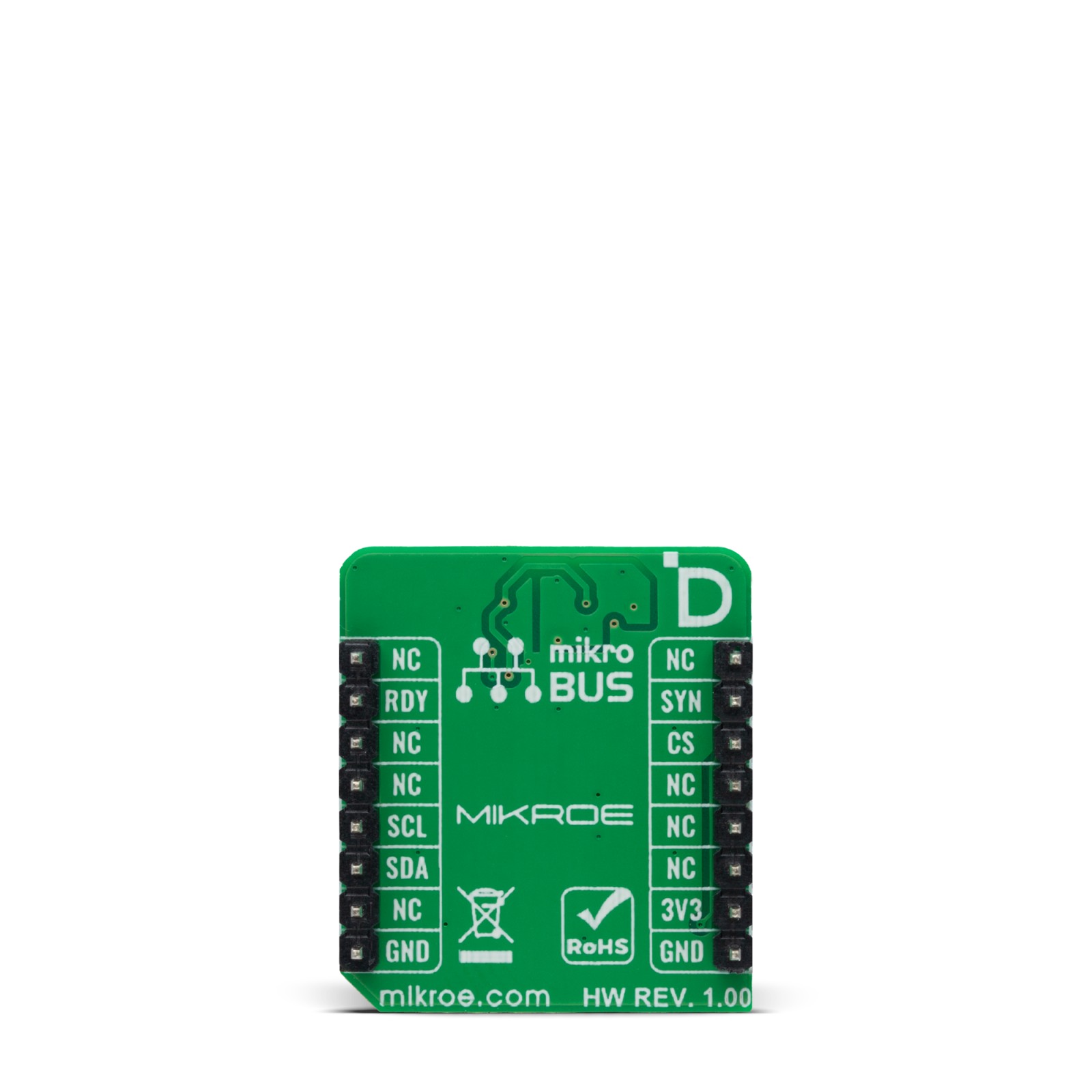
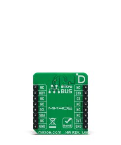
This table shows how the pinout on UV 5 Click corresponds to the pinout on the mikroBUS™ socket (the latter shown in the two middle columns).
Onboard settings and indicators
Label | Name | Default | Description |
---|---|---|---|
LD1 | PWR | – | Power LED Indicator |
A0-A1 | ADDR SEL | Left | I2C Address Selection 0/1: Left position 0, Right position 1 |
UV 5 Click electrical specifications
Description | Min | Typ | Max | Unit |
---|---|---|---|---|
Supply Voltage | – | 3.3 | – | V |
Peak Wavelength (A/B/C) | – | 260/300/360 | – | nm |
ADC Resolution | 10 | – | 24 | bit |
Software Support
We provide a library for the UV 5 Click as well as a demo application (example), developed using MIKROE compilers. The demo can run on all the main MIKROE development boards.
Package can be downloaded/installed directly from NECTO Studio Package Manager (recommended), downloaded from our LibStock™ or found on Mikroe github account.
Library Description
This library contains API for UV 5 Click driver.
Key functions
-
uv5_get_rdy_pin
UV 5 get READY pin state function. -
uv5_sw_reset
UV 5 software reset function. -
uv5_channel_uva_read
UV 5 read raw UVA data function.
Example Description
This example demonstrates the use of UV 5 Click board™ by measuring the light irradiance of the UVA, UVB and UVC.
void application_task ( void )
{
float temp_data;
uint16_t uv_raw_data;
float uv_data;
if ( uv5_get_rdy_pin( &uv5 ) == 1 )
{
uv5_temperature_read( &uv5, &temp_data );
log_printf( &logger, " Temp: %.2f degCrn", temp_data );
uv5_channel_uva_read( &uv5, &uv_raw_data );
uv_data = ( float ) ( ( FSRE_UVA / OUTCONV ) * uv_raw_data );
log_printf( &logger, " UVA: %.2f uW/cm2 rn", uv_data );
uv5_channel_uvb_read( &uv5, &uv_raw_data );
uv_data = ( float ) ( ( FSRE_UVB / OUTCONV ) * uv_raw_data );
log_printf( &logger, " UVB: %.2f uW/cm2 rn", uv_data );
uv5_channel_uvc_read( &uv5, &uv_raw_data );
uv_data = ( float ) ( ( FSRE_UVC / OUTCONV ) * uv_raw_data );
log_printf( &logger, " UVC: %.2f uW/cm2 rn", uv_data );
log_printf( &logger, " =================== rn" );
}
}
The full application code, and ready to use projects can be installed directly from NECTO Studio Package Manager (recommended), downloaded from our LibStock™ or found on Mikroe github account.
Other Mikroe Libraries used in the example:
- MikroSDK.Board
- MikroSDK.Log
- Click.UV5
Additional notes and informations
Depending on the development board you are using, you may need USB UART click, USB UART 2 Click or RS232 Click to connect to your PC, for development systems with no UART to USB interface available on the board. UART terminal is available in all MIKROE compilers.
mikroSDK
This Click board™ is supported with mikroSDK – MIKROE Software Development Kit. To ensure proper operation of mikroSDK compliant Click board™ demo applications, mikroSDK should be downloaded from the LibStock and installed for the compiler you are using.
For more information about mikroSDK, visit the official page.