How does it work?
USB I2C Click is based on the MCP2221A, a USB 2.0 to I2C/UART protocol converter with GPIO from Microchip. The heart of the MCP2221A is the Bus Matrix module that controls and manages all data transfers between the USB, the UART, and the I2C. It also takes care of the command requests generated by the USB host controller and commands for controlling the UART, GPIO, ADC, DAC, and clock output functions. The 448-byte buffer can handle data throughput at any supported UART baud rate with 64-byte TX and 384-byte RX. The Human Interface Device standard can count on a 64-byte buffer to handle data throughput at any I2C baud rate.
The USB HID and CDC modules in the MCP2221A are full-speed USB 2.0 compliant, with fully configurable VID and PID assignments and stored on-chip descriptors. The USB Transceiver obtains power internally connected to the 3.3V regulator, the AP7331, of the USB I2C Click board. The MCP2221A can be bus-powered or self-powered; it can be powered through the mikroBUS™ socket or over the mini-USB connector.
The USB I2C Click can use UART or I2C interface to communicate to the host MCU over the mikroBUS™ socket. These two interfaces exist concurrently and can be selected independently according to the application. The I2C interface acts as an I2C Master, and the data to Write/Read on the I2C bus is conveyed by the USB interface that can read/write blocks of up to 65.535 bytes long, with up to 400KHz clock rate.
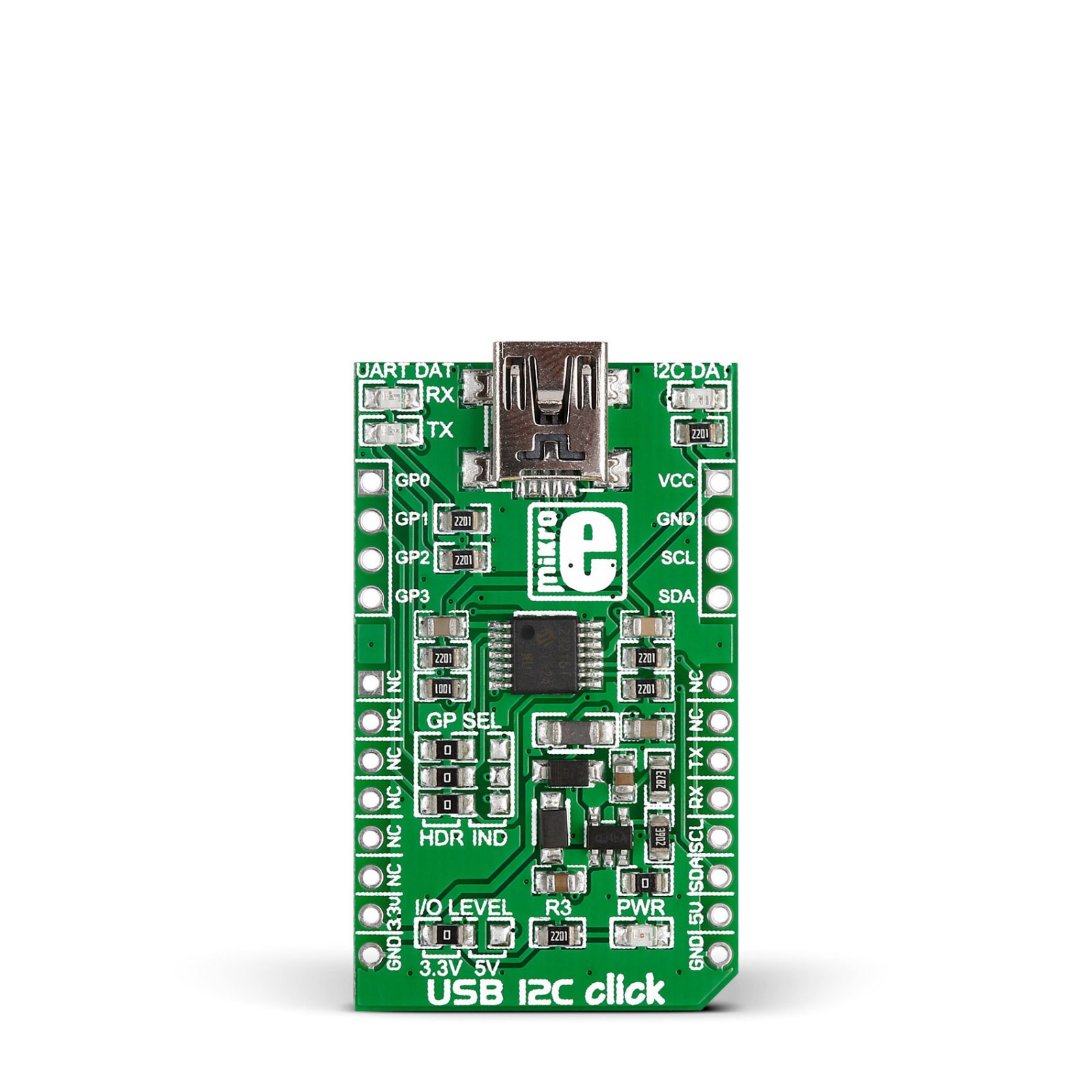
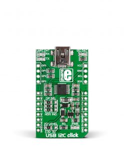
This Click board™ features two 4-pin headers on the board’s edges with additional GPIOs (GP0-GP3) and I2C pins plus VCC and GND. Those GPIO pins can be used as general-purpose I/O or alternate functions such as ADC, DAC, and IOC (external interrupt edge detector). The board also features UART DAT RX, TX LEDs, and I2C DAT status LEDs. To use these LEDs, you must select IND on the GP SEL jumper (the HDR is selected by default). If so, the GP0, GP1, and GP3 can not be used as GPIO on the HD1 header.
This Click board™ can operate with either 3.3V or 5V logic voltage levels selected via the VCC SEL jumper. This way, both 3.3V and 5V capable MCUs can use the communication lines properly. However, the Click board™ comes equipped with a library containing easy-to-use functions and an example code that can be used as a reference for further development.
Specifications
Type
USB
Applications
Can be used for adding a USB to UART or I2C conversion to the application
On-board modules
MCP2221A – USB 2.0 to I2C/UART protocol converter with GPIO from Microchip
Key Features
Full speed HID class USB device, USB 2.0 compliant with entire USB protocol handled on the chip, supported by most operation systems, custom driver is not required, I2C Master interface, standalone operation, and more
Interface
I2C,UART,USB
Feature
No ClickID
Compatibility
mikroBUS™
Click board size
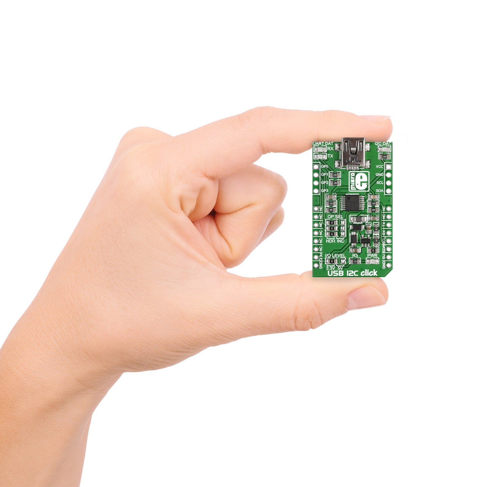
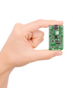
M (42.9 x 25.4 mm)
Input Voltage
3.3V or 5V
Pinout diagram
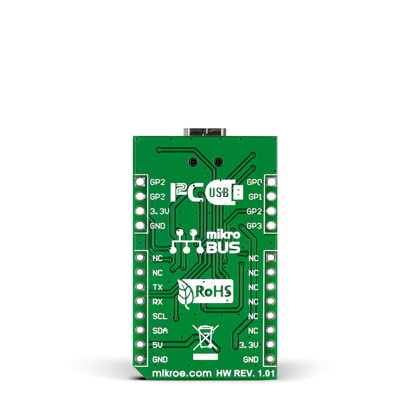
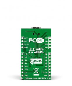
This table shows how the pinout on USB I2C Click corresponds to the pinout on the mikroBUS™ socket (the latter shown in the two middle columns).
Onboard settings and indicators
Label | Name | Default | Description |
---|---|---|---|
– | PWR | – | Power LED Indicator |
– | RX/TX | – | UART RX/TX LED Indicators |
– | I2C DAT | – | I2C Traffic LED Indicator |
– | VCC SEL | Left | Logic Level Voltage Selection 3V3/5V: Left position 3V3, Right position 5V |
J2-J4 | GP SEL | Left | GPIO Usage Selection HDR/IND: Left position HDR, Right position IND |
HD1 | – | Unpopulated | General-Purpose I/O Pins |
HD2 | – | Unpopulated | Additional I2C Interface Pins |
USB I2C Click electrical specifications
Description | Min | Typ | Max | Unit |
---|---|---|---|---|
Supply Voltage | 3.3 | – | 5 | V |
Data Rate | – | – | 12 | Mbps |