How does it work?
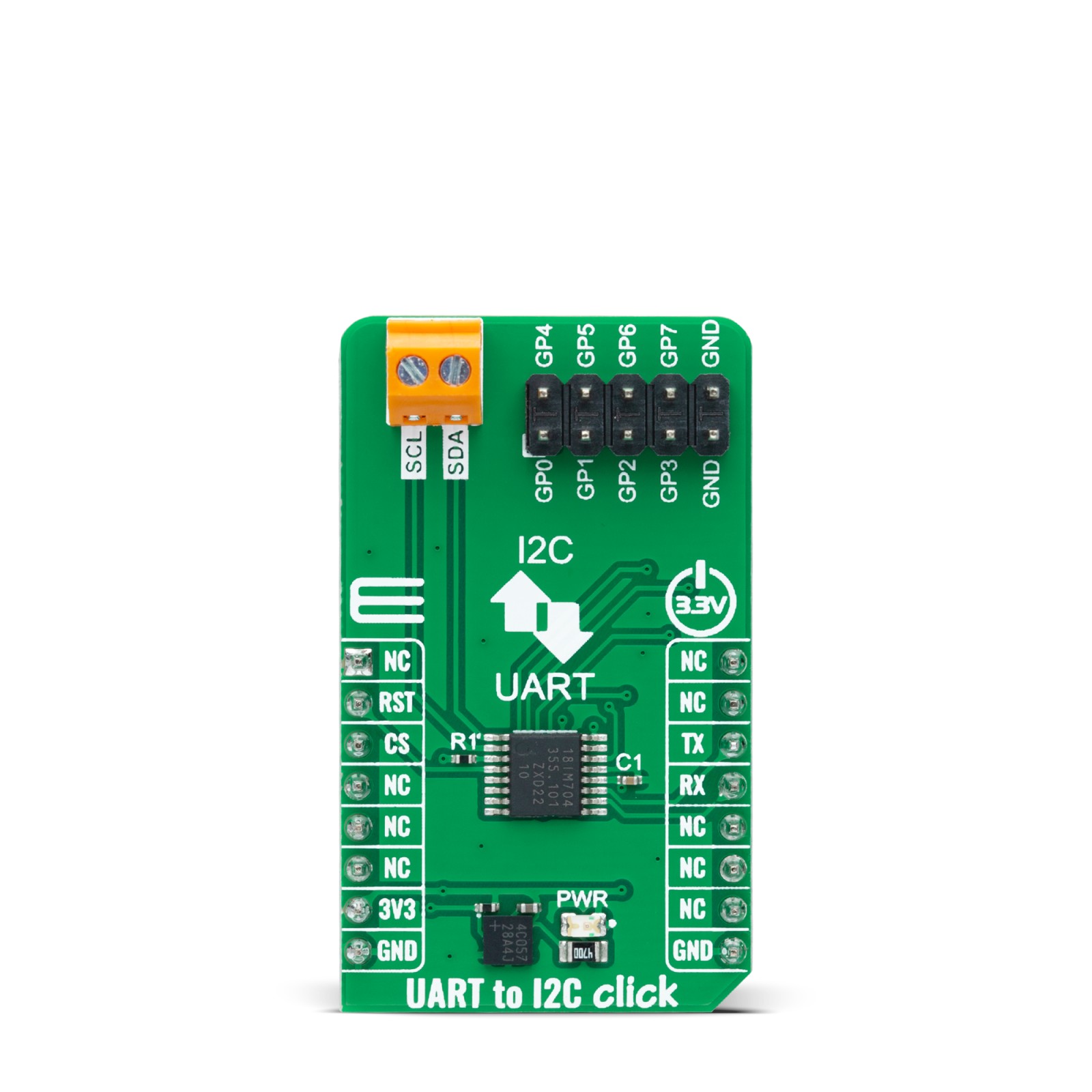
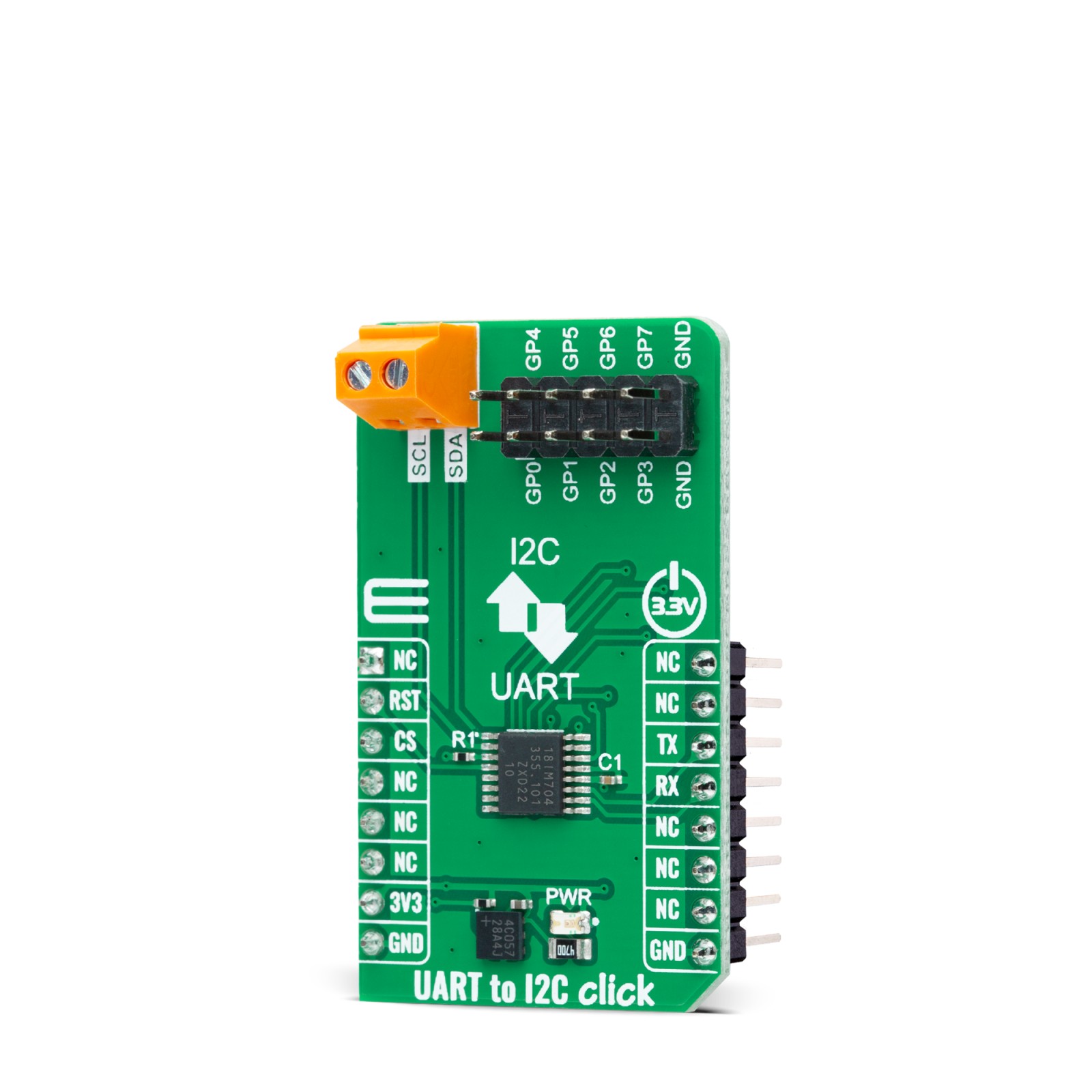
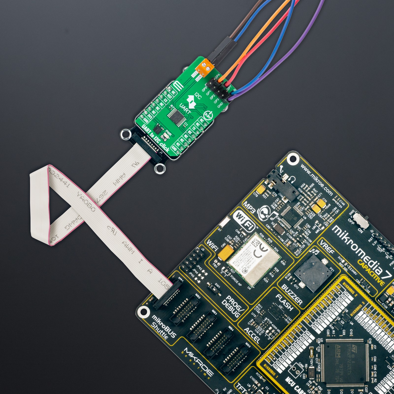
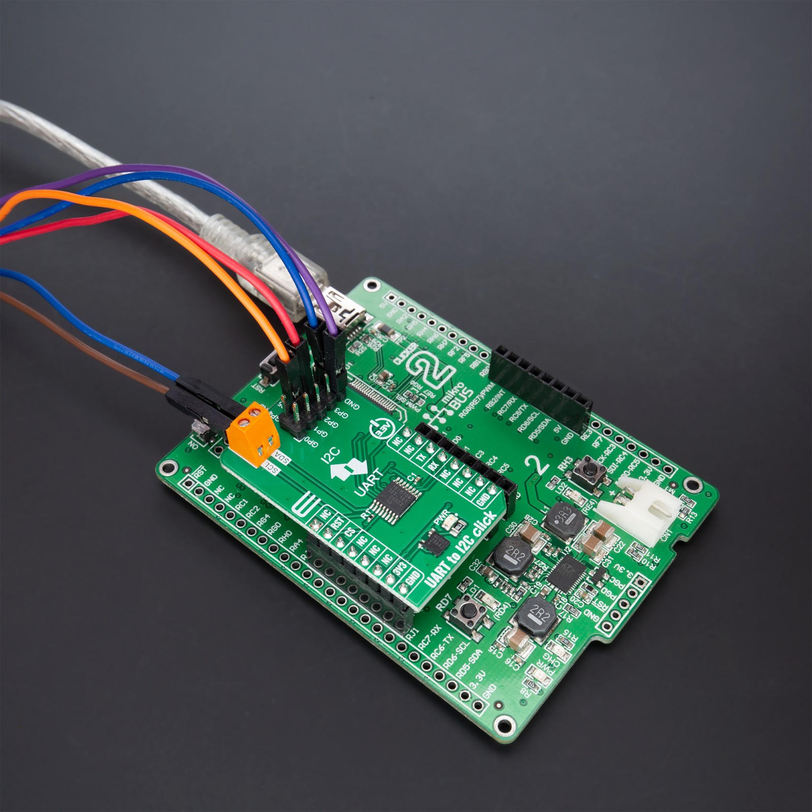
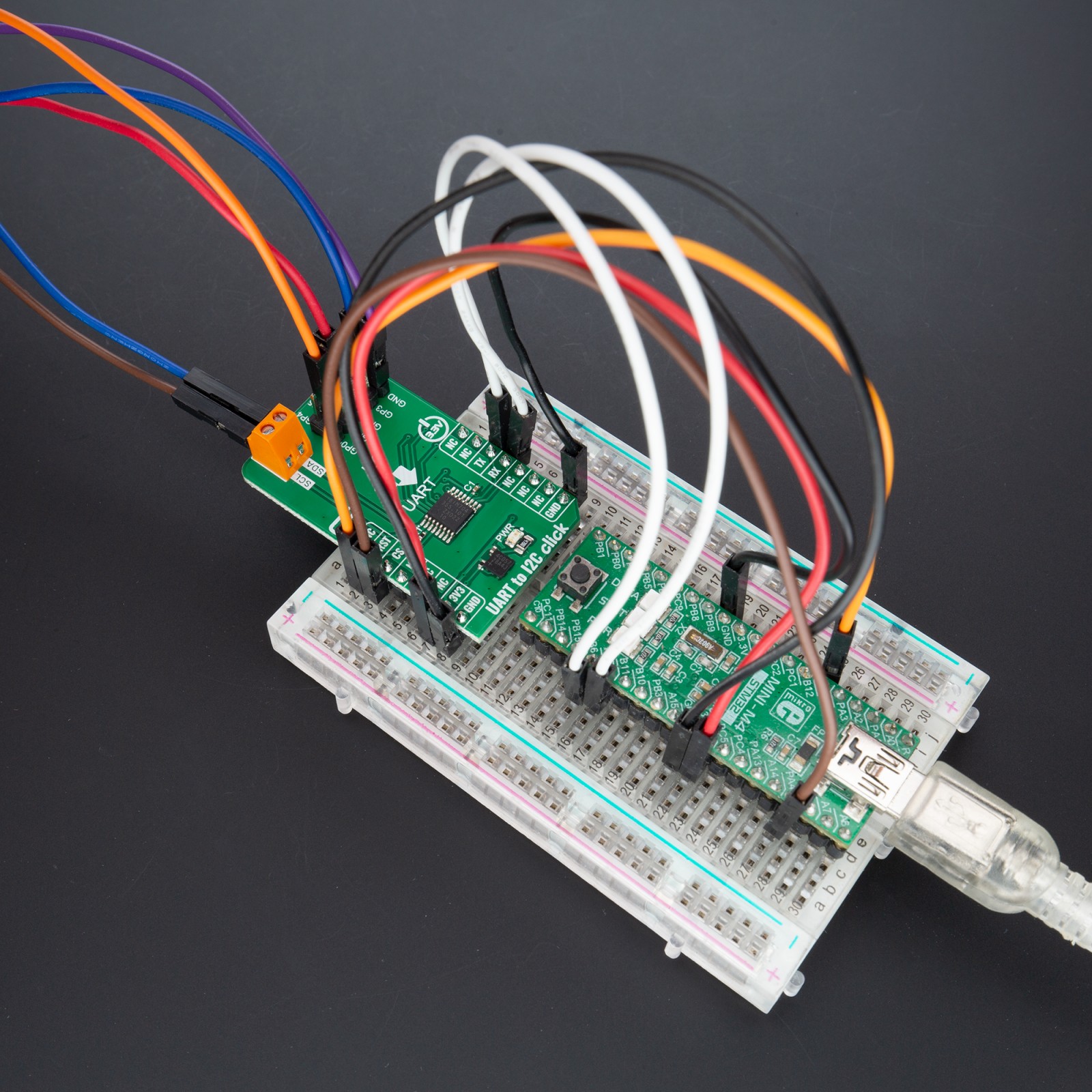
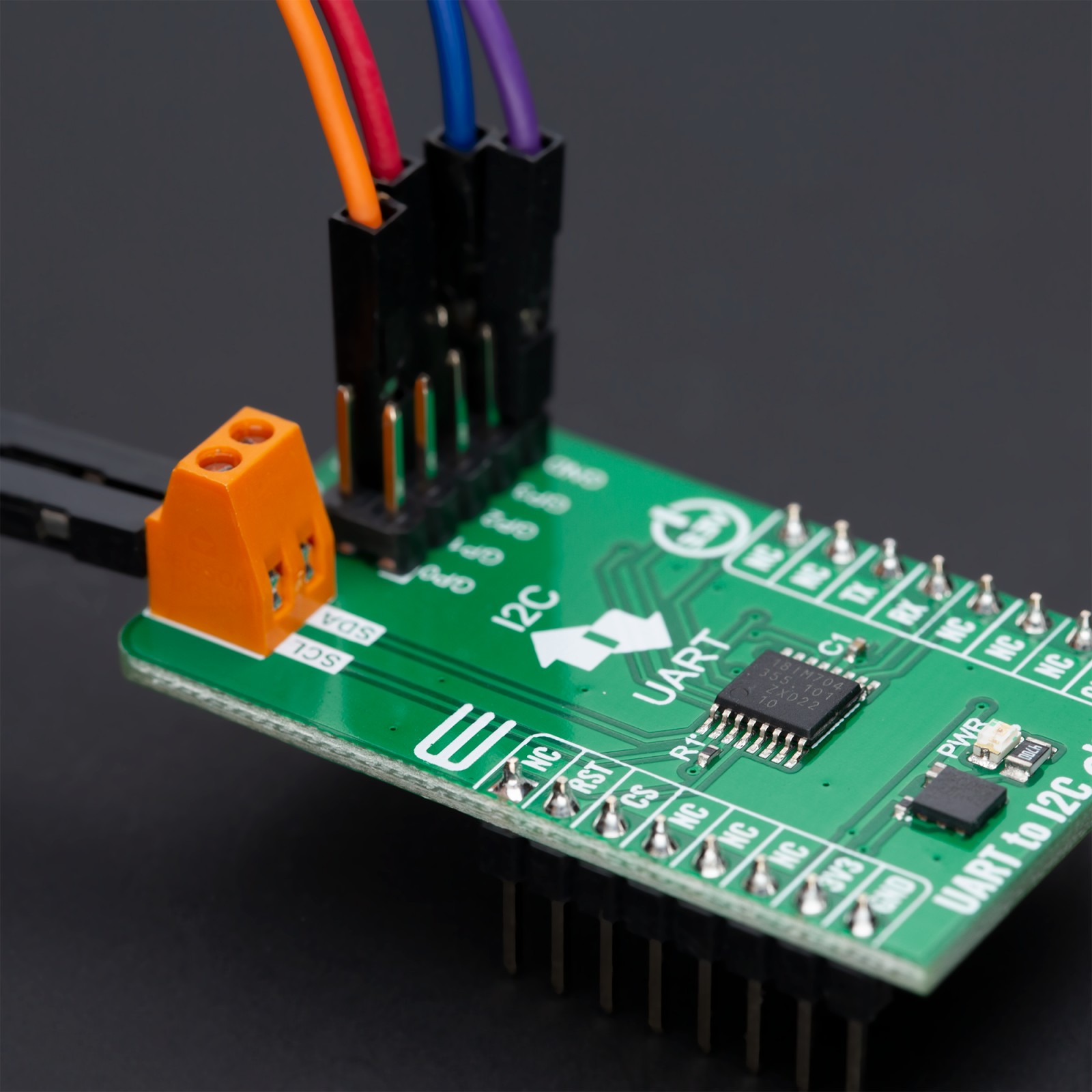
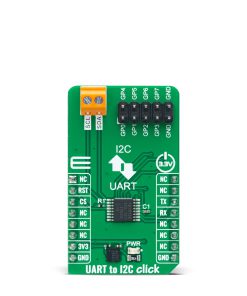
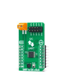
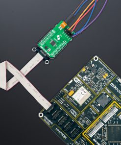
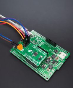
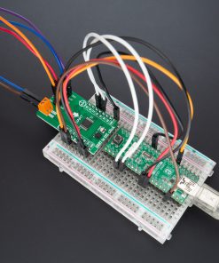
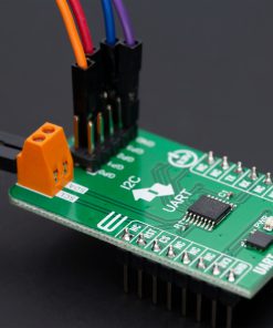
UART to I2C Click is based on the SC18IM704, a bridge between the standard UART port and a serial I2C bus from NXP Semiconductors. The SC18IM704 consists of a full-functional advanced UART interface that communicates with the host MCU through the commonly-used RX and TX pins of the mikroBUS™ socket. It is also characterized by a high baud rate of up to 460.8 kbit/s and 256-byte FIFO for the transfer/receive data process. The serial data format is fixed to a one start bit, 8 data bits, and one stop bit. After the reset feature, the baud rate defaults to 9600 bit/s and can be changed through the Baud Rate Generator (BRG) registers.
After a Power-Up sequence or already-mentioned hardware reset, achievable through the RST pin of the mikroBUS™ socket, the SC18IM704 will send two continuous bytes to the host MCU to indicate a Start-Up condition. These two continuous bytes are 0x4F and 0x4B, representing an ‘OK’ state in the ASCII messages protocol. After the correct initial sequence, direct communication is enabled with other I2C-bus devices connected to the populated I2C-bus terminal. The I2C bus uses two wires (SCL and SDA) to transfer information between connected devices, providing a byte-oriented interface that supports data transfers up to 400kHz.
The SC18IM704 can also be placed in a software-configurable low-power mode (Power-Down mode). Upon entering the Power-Down state, the UART RX pin is used to exit Deep Power-down mode. The bridge remains in the Deep Power-down mode as long as the RX pin remains in a high logic state. Any character sent brings the bridge out of Deep Power-down mode but ignores the character. In addition to all these features, the SC18IM704 has several general-purpose I/O pins on the populated header with labeled GP pins. These pins have the option of software setting their function as push-pull, open-drain, or input-only.
This Click board™ can be operated only with a 3.3V logic voltage level. The board must perform appropriate logic voltage level conversion before using MCUs with different logic levels. However, the Click board™ comes equipped with a library containing functions and an example code that can be used as a reference for further development.
Specifications
Type
I2C
Applications
Can be used for industrial applications such as communication bridges, process and automation control, I2C bus support, and more
On-board modules
SC18IM704 – bridge between UART port and a serial I2C bus from NXP Semiconductors
Key Features
High speed UART host interface, programmable I/O pins, 256-byte TX/RX FIFO, programmable baud rate, Power-down mode, UART ASCII messages protocol, Reset, and more
Interface
UART
Feature
ClickID
Compatibility
mikroBUS™
Click board size
M (42.9 x 25.4 mm)
Input Voltage
3.3V
Pinout diagram
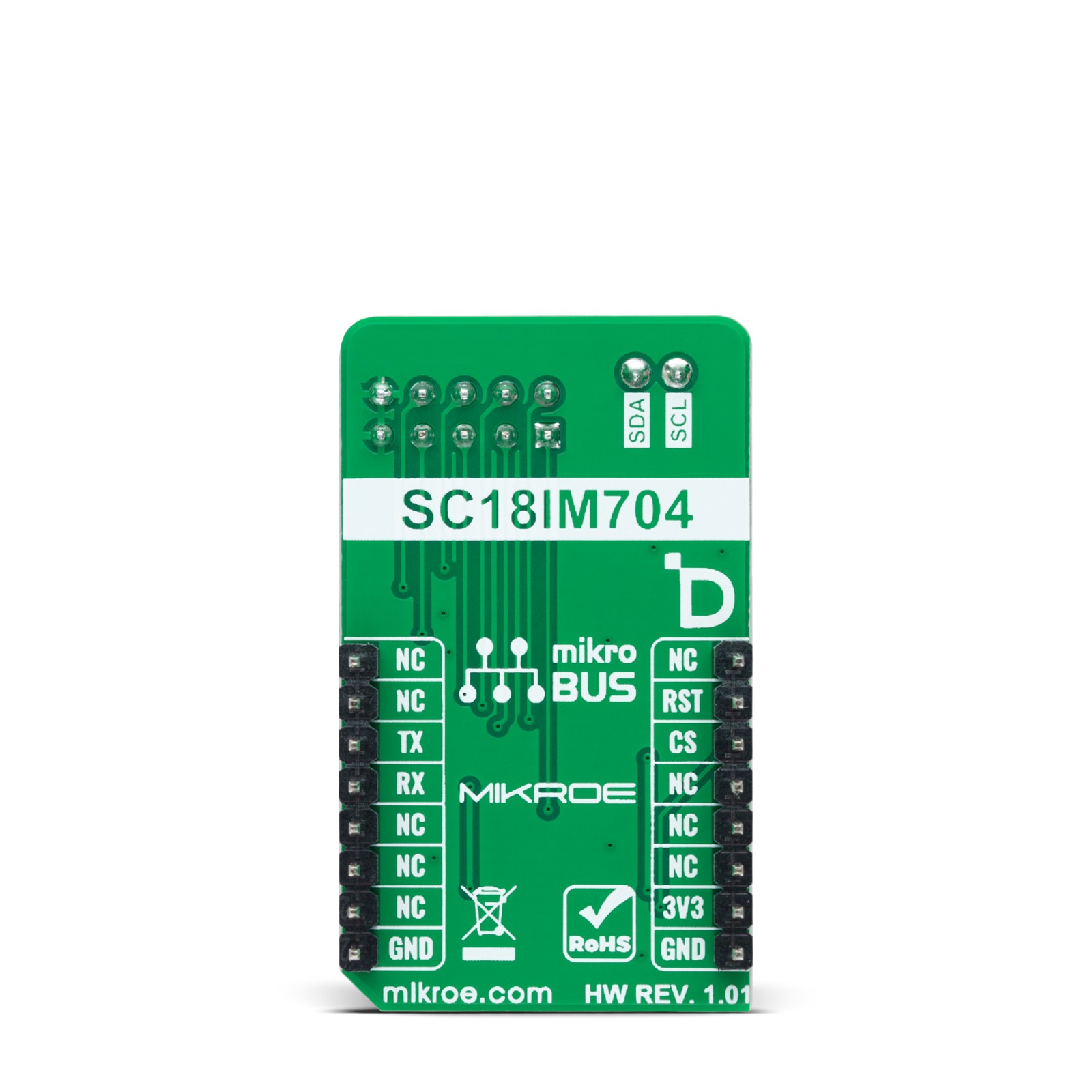
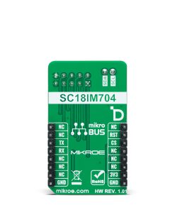
This table shows how the pinout on UART to I2C Click corresponds to the pinout on the mikroBUS™ socket (the latter shown in the two middle columns).
Onboard settings and indicators
Label | Name | Default | Description |
---|---|---|---|
LD1 | PWR | – | Power LED Indicator |
J1 | GP | Populated | User-Configurable I/O Pins Header |
UART to I2C Click electrical specifications
Description | Min | Typ | Max | Unit |
---|---|---|---|---|
Supply Voltage | – | 3.3 | – | V |
Software Support
We provide a library for the UART to I2C Click as well as a demo application (example), developed using Mikroe compilers. The demo can run on all the main Mikroe development boards.
Package can be downloaded/installed directly from NECTO Studio Package Manager (recommended), downloaded from our LibStock™ or found on Mikroe github account.
Library Description
This library contains API for UART to I2C Click driver.
Key functions
-
uarttoi2c_gpio_write
This function writes a desired data to the gpio port. -
uarttoi2c_gpio_read
This function reads data from the gpio port. -
uarttoi2c_i2c_write_then_read
This function performs a write then read with a repeated start to the I2C target device.
Example Description
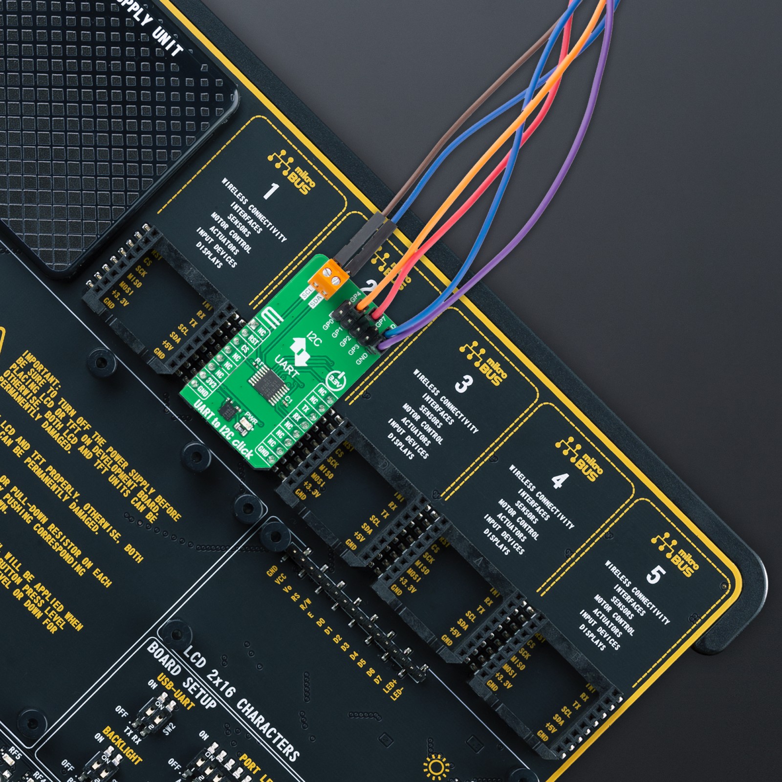
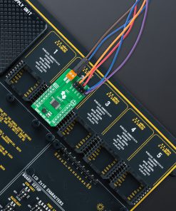
This example demonstrates the use of USB to I2C Click board™ by reading the device ID of a 3D Hall 11 Click board™ connected to the I2C port and controlling the GPIO pins.
void application_task ( void )
{
static uint8_t gpio_state = UARTTOI2C_NO_PIN_MASK;
uint8_t slave_address = DEVICE_SLAVE_ADDRESS;
uint8_t reg_addr = DEVICE_REG_ID;
uint8_t device_id;
if ( UARTTOI2C_OK == uarttoi2c_i2c_write_then_read ( &uarttoi2c, slave_address,
®_addr, 1, &device_id, 1 ) )
{
log_printf( &logger, " %s - Device ID read: %srn", ( char * ) DEVICE_NAME,
( char * ) ( ( DEVICE_ID == device_id ) ? "Success" : "Fail" ) );
}
uarttoi2c_gpio_write ( &uarttoi2c, gpio_state );
if ( UARTTOI2C_OK == uarttoi2c_gpio_read ( &uarttoi2c, &gpio_state ) )
{
log_printf( &logger, " GPIO state: 0x%.2Xrnn", ( uint16_t ) gpio_state );
gpio_state = ~gpio_state;
}
Delay_ms ( 1000 );
}
The full application code, and ready to use projects can be installed directly from NECTO Studio Package Manager (recommended), downloaded from our LibStock™ or found on Mikroe github account.
Other Mikroe Libraries used in the example:
- MikroSDK.Board
- MikroSDK.Log
- Click.UARTtoI2C
Additional notes and informations
Depending on the development board you are using, you may need USB UART click, USB UART 2 Click or RS232 Click to connect to your PC, for development systems with no UART to USB interface available on the board. UART terminal is available in all Mikroe compilers.
mikroSDK
This Click board™ is supported with mikroSDK – Mikroe Software Development Kit. To ensure proper operation of mikroSDK compliant Click board™ demo applications, mikroSDK should be downloaded from the LibStock and installed for the compiler you are using.
For more information about mikroSDK, visit the official page.