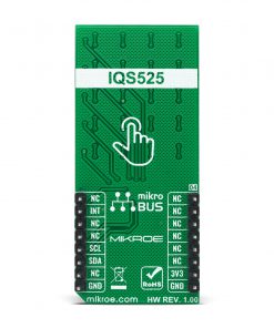
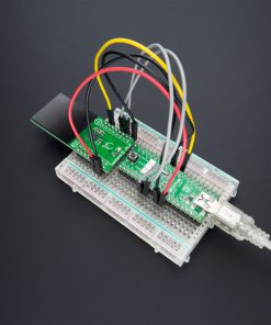
How does it work?
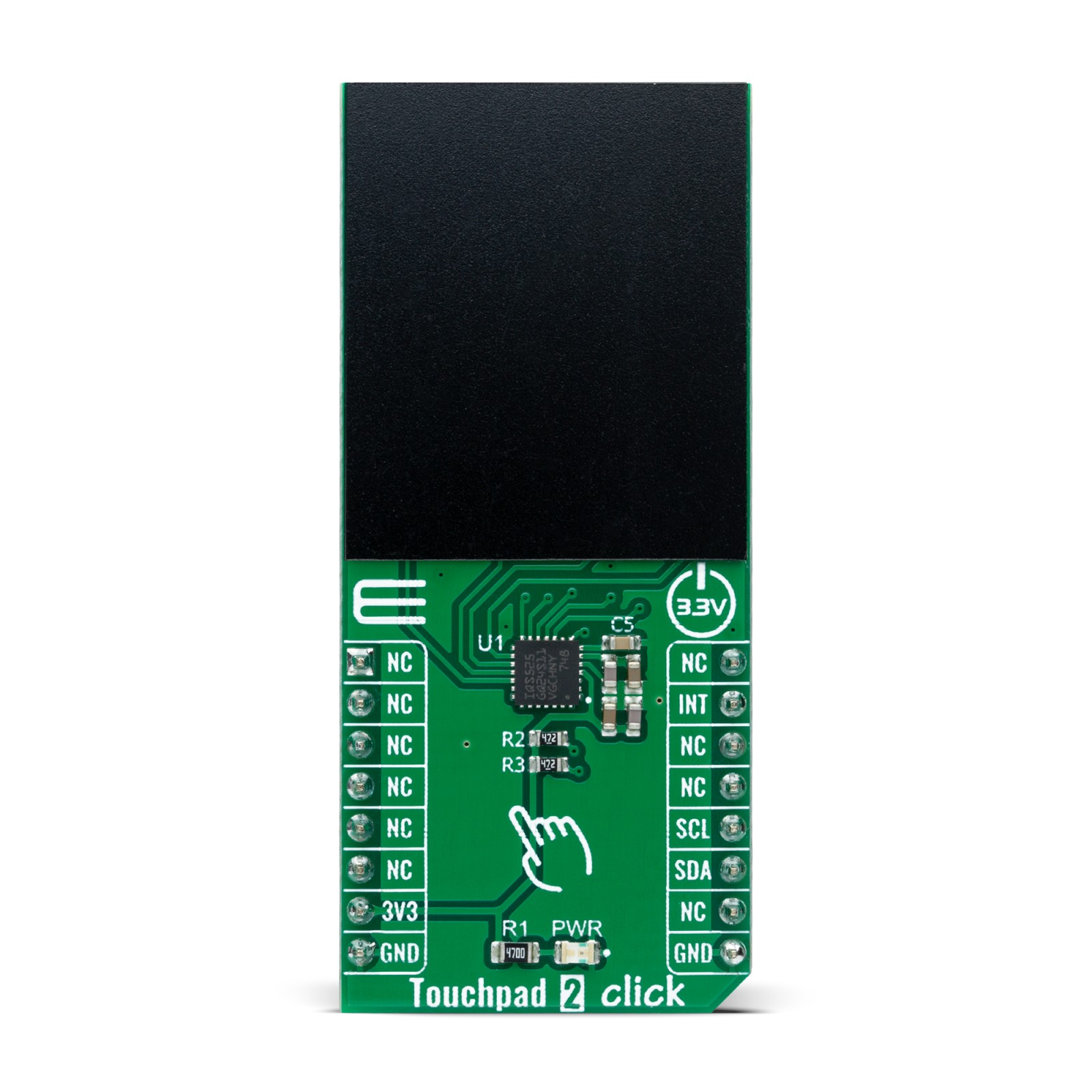
Touchpad 2 Click as its foundation uses the IQS525, a capacitive sensing controller designed for multitouch application using projected capacitance touch panel from Azoteq. It offers high sensitivity proximity/hover detection and contact (touch) detection. The device has an internal voltage regulator and Internal Capacitor Implementation (ICI) to reduce external components, which can be noticed on the Click board™ (very few additional components required by this IC). Advanced integrated signal processing capabilities yield a stable, high-performance capacitive controller with high sensitivity.
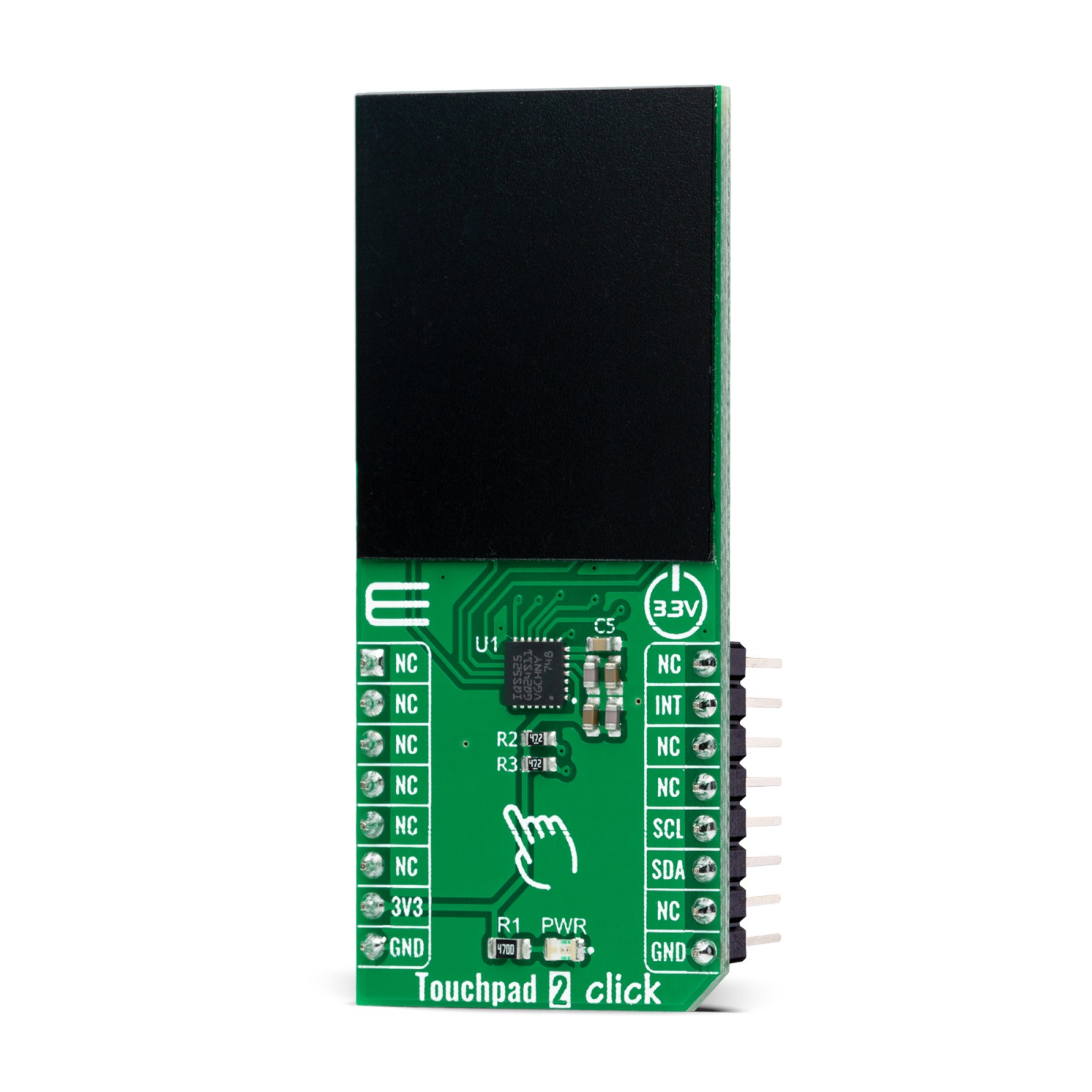
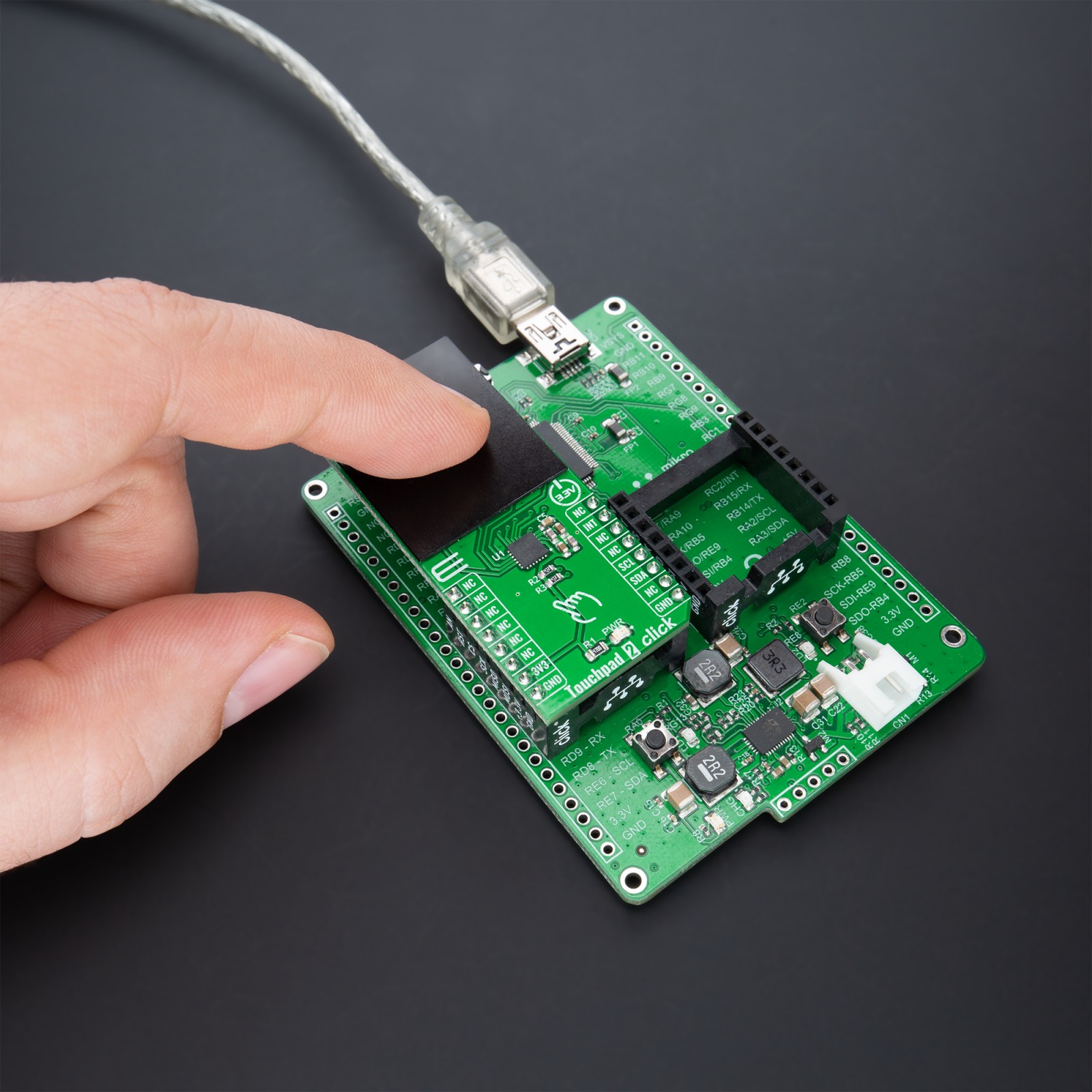
On the front side of the Touchpad 2 Click, there is a clearly defined field that represents a touchpad area. This area is a matrix of conductive electrodes on the PCB, electrically isolated from each other, arranged as rows and columns of X and Y. An electrode consists of multiple diamond-shaped elements, each connected to the next with a conductive neck.
The controller uses the principle of projected capacitance charge transfer on the touchpad area. When a conductive object such as a human finger approaches the sense plate, it will decrease the detected capacitance. Observing the measured results at various sensing points on the touchpad area enables the controller to determine proximity/hover detection and contact (touch) detection on all channels and accurately determine the coordinates on the touch area.
Due to the advanced sensitivity of the IQS525, multiple non-contact (proximity hover) coordinates also can be obtained. These hover coordinates can predict the touch coordinate of an approaching user before the touch is made, allowing innovative user interface options. Multiple filters are implemented to suppress, detect noise, and track slow varying environmental conditions and avoid effects of possible drift.
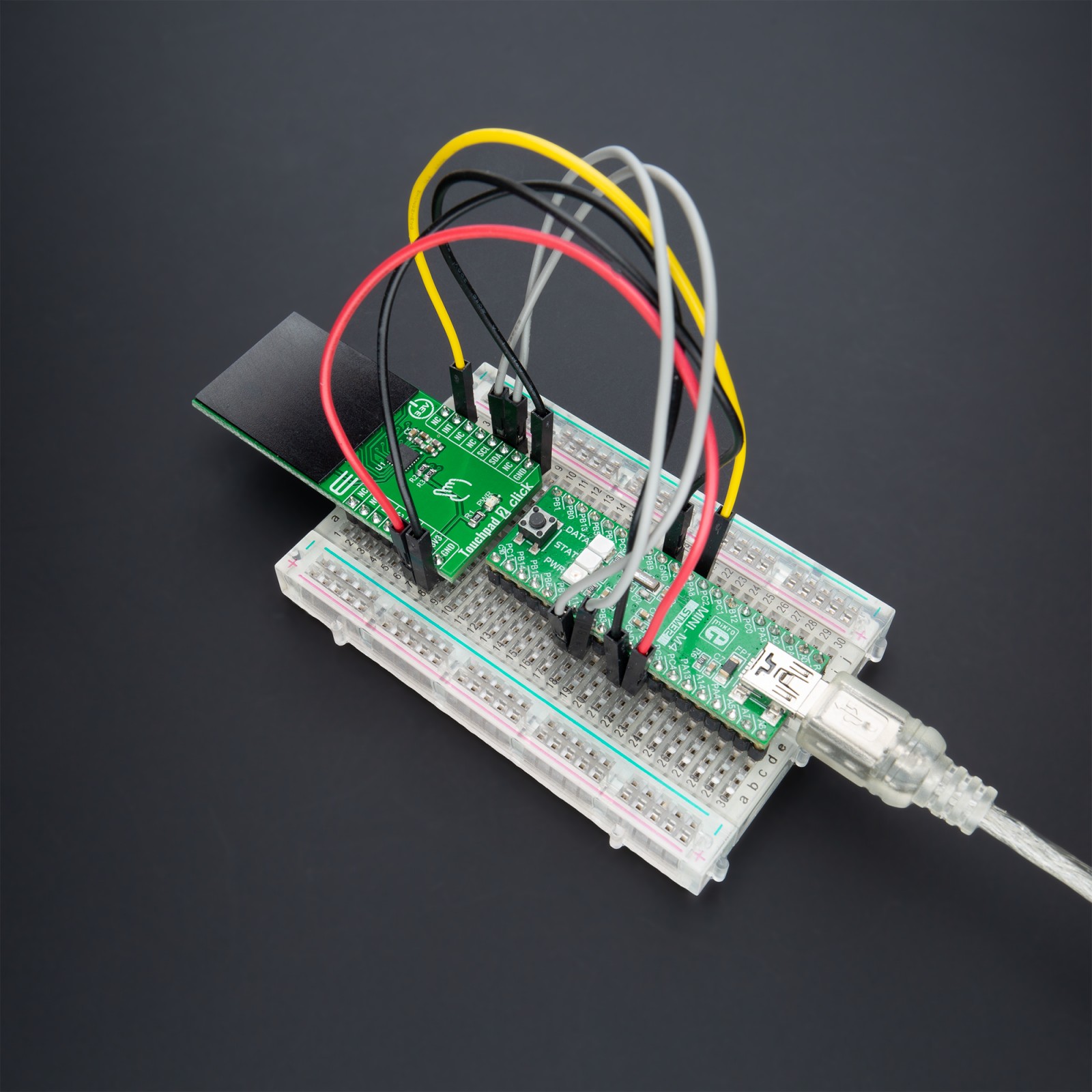
Touchpad 2 Click communicates with MCU using a standard I2C 2-Wire interface, with a clock frequency up to 100kHz in the Standard and 400kHz in the Fast Mode. An additional ready signal, routed on the INT pin of the mikroBUS™ socket, is added, which indicates when the communication window is available. Thus, it is optimal for the response rate to use the INT pin as a communication trigger, but polling is also a less attractive option.
This Click board™ can be operated only with a 3.3V logic voltage level. The board must perform appropriate logic voltage level conversion before use with MCUs with different logic levels. However, the Click board™ comes equipped with a library containing functions and an example code that can be used, as a reference, for further development.
Specifications
Type
Capacitive
Applications
Can be used for human-machine interfaces, keypad or scrolling functions, single-finger gesture-based interfaces, and more.
On-board modules
IQS525 – capacitive sensing controller designed for multitouch application using projected capacitance touch panel from Azoteq
Key Features
Multi-touch and multi-hover support, automatic drift compensation, embedded gesture engine recognition for simple gestures (tap, swipes, hold), and more.
Interface
I2C
Feature
No ClickID
Compatibility
mikroBUS™
Click board size
L (57.15 x 25.4 mm)
Input Voltage
3.3V
Pinout diagram
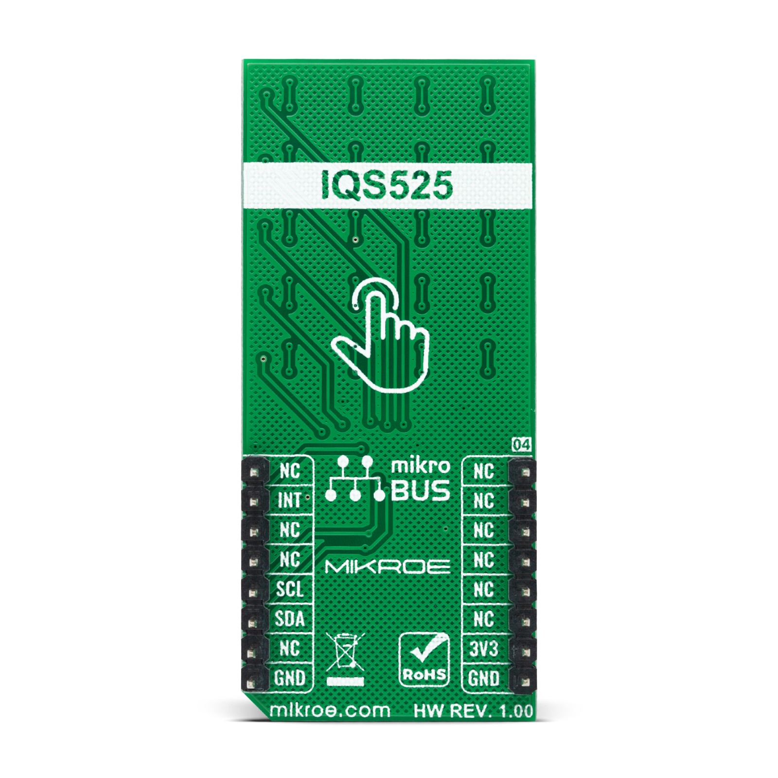
This table shows how the pinout on Touchpad 2 Click corresponds to the pinout on the mikroBUS™ socket (the latter shown in the two middle columns).
Onboard settings and indicators
Label | Name | Default | Description |
---|---|---|---|
LD1 | PWR | – | Power LED Indicator |
Touchpad 2 Click electrical specifications
Description | Min | Typ | Max | Unit |
---|---|---|---|---|
Receiver inputs voltage range | – | 3.3 | – | V |
Receiver inputs voltage range | – | 16 | – | bit |
Receiver inputs voltage range | -40 | +25 | +85 | °C |
Software Support
We provide a library for the Touchpad 2 Click as well as a demo application (example), developed using MikroElektronika compilers. The demo can run on all the main MikroElektronika development boards.
Package can be downloaded/installed directly from NECTO Studio Package Manager (recommended way), downloaded from our LibStock™ or found on mikroE github account.
Library Description
This library contains API for Touchpad 2 Click driver.
Key functions:
touchpad2_cfg_setup
– Config Object Initialization function.touchpad2_init
– Initialization function.touchpad2_default_cfg
– Click Default Configuration function.
Examples description
This library contains API for the Touchpad 2 Click driver. The library contains drivers to get touch details, the number of touches, X and Y coordinates and touch strength.
The demo application is composed of two sections :
void application_task ( void ) { touchpad2_wait_ready( &touchpad2 ); touchpad2_get_touch ( &touchpad2, &touch_data ); Delay_ms( 100 ); if ( ( touch_data.id_tag == TOUCHPAD2_ID_TAG_TOUCH_1 ) || ( touch_data.id_tag == TOUCHPAD2_ID_TAG_TOUCH_2 ) || ( touch_data.id_tag == TOUCHPAD2_ID_TAG_TOUCH_3 ) || ( touch_data.id_tag == TOUCHPAD2_ID_TAG_TOUCH_4 ) || ( touch_data.id_tag == TOUCHPAD2_ID_TAG_TOUCH_5 ) ) { log_printf( &logger, " Number of touches : %d rn", ( uint16_t ) touch_data.no_of_fingers ); log_printf( &logger, "- - - - - - - - - - - - -rn" ); log_printf( &logger, " Coordinate X = %d rn", touch_data.x_pos ); log_printf( &logger, " Coordinate Y = %d rn", touch_data.y_pos ); log_printf( &logger, "- - - - - - - - - - - - -rn" ); log_printf( &logger, " Touch Strength : %u rn", ( uint16_t ) touch_data.touch_str ); log_printf( &logger, "------------------------ rn" ); Delay_ms( 500 ); } }
The full application code, and ready to use projects can be installed directly from NECTO Studio Package Manager(recommended way), downloaded from our LibStock™ or found on mikroE github account.
Other mikroE Libraries used in the example:
- MikroSDK.Board
- MikroSDK.Log
- Click.TouchPad2
Additional notes and informations
Depending on the development board you are using, you may need USB UART click, USB UART 2 click or RS232 click to connect to your PC, for development systems with no UART to USB interface available on the board. The terminal available in all MikroElektronika compilers, or any other terminal application of your choice, can be used to read the message.
mikroSDK
This Click board™ is supported with mikroSDK – MikroElektronika Software Development Kit. To ensure proper operation of mikroSDK compliant Click board™ demo applications, mikroSDK should be downloaded from the LibStock and installed for the compiler you are using.
For more information about mikroSDK, visit the official page.