

TMR mix-sens click
R425.00 ex. VAT
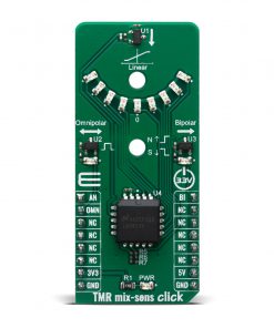
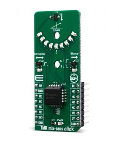
The TMR mix-sens Click is an add-on board equipped with the TMR digital push-pull and analog magnetic sensors, as well as intensity of magnetic field indicator. The TMR mix-sens Click has three types of magnetic field sensors: Two digital and one analog sensor. The digital sensors are the RR122-1A22-511 which has an omnipolar polarity response, and the RR122-3C63-511 which has a bipolar polarity response. The analog sensor is the RR112-1G43-531, which outputs a voltage that is proportional to magnetic field. The board also has an LM3914 voltage level indicator, which takes the output voltage of the RR112-1G43-531 sensor and uses it to light a series of LEDs to indicate the level of magnetic field seen by the sensor. All sensor outputs can be accessed through mikroBUS I/O or analog pins, also they are visually represented over on-board LED’s. This board can be used for evaluation of the TMR sensors as well as for testing applications which are requiring low power wake up functionality.
TMR mix-sens Click is supported by a mikroSDK compliant library, which includes functions that simplify software development. This Click board™ comes as a fully tested product, ready to be used on a system equipped with the mikroBUS™ socket.
NOTE: With the board you will also receive cylindrical magnets for performing out of the box testing.
Stock: Lead-time applicable.
| 5+ | R403.75 |
| 10+ | R382.50 |
| 15+ | R361.25 |
| 20+ | R347.65 |
TMR mix-sens Click provides three different Coto Technology RedRock™ TMR magnetic sensors that can be operated with supplied magnets and provide instantaneous visual feedback through LED’s that indicate sensor output. These sensors utilize tunneling Magnetoresistance (TMR) technology that provides the lowest power consumption and highest magnetic sensitivity of any available magnetic sensor. With the board you will also receive cylindrical magnets for performing out of the box testing. To get started, you’ll need to supply 3.3V and 5V to the corresponding pins (see image below).
How does it work?
The first sensor on this Click board, a Coto Technology RedRock RR122-1A22-511 is an ominpolar, 9 Gauss operate, 10Hz sensing frequency, push pull output sensor that consumes an average of only 240nA. This sensor is often used for proximity detection or as a means to signal a battery operated device to wake up or power on. The second sensor on this Click board is an RR122-3C63-511 which is a bi-polar, 10 Gauss operate/-10 Gauss release, 500Hz sensing frequency, push pull output sensor that consumes an average of 1.7uA. This sensor is often used for rotation counting. The third sensor on this Click board is an RR112-1G43-531 which provides a linear voltage output that is proportional to a magnetic field strength between -10 and 10 Gauss with a sensitivity of -20 mv/V/G and 1.5mA average supply current. This sensor is typically used in level or distance sensing applications and can provide a distance resolution of 1mm.

In addition to being able to access the outputs of the three sensors through the mikroBUS and get information to the host MCU, a visual confirmation of the activation and deactivation of each sensor is provided by means of LEDs placed next to each of the sensors on the board. When operating these sensors with the supplied magnets or magnets of your choosing, the LED’s associated with each sensor will activate to visually indicate the sensing of a magnetic field. The LED2 for the RR122-1A22-511 lights up when the operate field strength of 9 Gauss is reached and subsequently turns off when the release field strength of 5 Gauss is reached, providing a hysteresis of 4 Gauss. This can demonstrated by moving the North or South pole of magnet towards the sensor in the direction of the arrow. The LED3 for the RR122-3C63-511 lights up when a South pole field with a magnitude of 10 Gauss or greater is sensed and will stay lit until a North pole of 10 Gauss or higher is sensed. This can be demonstrated by bring in a magnet with one polarity and then reversing it. It can also be demonstrated by rotating the supplied ring magnet in the hole adjacent to the sensor.
The semi-circular array of nine LEDs (LED4-LED12) on the top of the board are used for the RR112-1G43-531 sensor. Please refer to the image above for the LED numbering. These will light to indicate when the sensor sees a North field, a South field or no field, and the magnitude for each polarity. The middle LED (LD8) will light to indicate no magnetic field (voltage output of Vdd/2). An LM3914 is used for indicating strength of linear output of RR112-1G43-531 sensor. The operation of this sensor can be demonstrated by moving the North of South pole of the magnet towards the sensor in the direction of the magnet. Alternatively, it can be demonstrated by rotating the ring magnet in the hole adjacent to the sensor.
Holes on the TMR mix-sens Click can be used to ease the installation of rotatable magnet holders.
A diagram showing the output response of all three sensors can be seen in the image below:
.jpg)
Specifications
Type
Magnetic
Applications
Applications like proximity sensing, rotary sensing, level and linearly proportional detection in medical, industrial, automotive and consumer applications
On-board modules
RR111-1DC2-331, RR121-1A23-311, RR121-3C63-311 and LM3914
Key Features
Magnetic field multi sensors and indicators low power consumption
Interface
Analog,GPIO
Feature
No ClickID
Compatibility
mikroBUS™
Click board size
L (57.15 x 25.4 mm)
Input Voltage
3.3V,5V
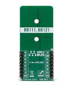
Pinout diagram
This table shows how the pinout on TMR mix-sens Click corresponds to the pinout on the mikroBUS™ socket (the latter shown in the two middle columns).
| Notes | Pin | Pin | Notes | ||||
|---|---|---|---|---|---|---|---|
| Liner Output | AN | 1 | AN | PWM | 16 | BI | Digital Bipolar Output |
| Digital Omnipolar Output | OMN | 2 | RST | INT | 15 | NC | |
| NC | 3 | CS | RX | 14 | NC | ||
| NC | 4 | SCK | TX | 13 | NC | ||
| NC | 5 | MISO | SCL | 12 | NC | ||
| NC | 6 | MOSI | SDA | 11 | NC | ||
| Power Supply | 3.3V | 7 | 3.3V | 5V | 10 | 5V | Power Supply |
| Ground | GND | 8 | GND | GND | 9 | GND | Ground |
Onboard settings and indicators
| Label | Name | Default | Description |
|---|---|---|---|
| LD1 | PWR | – | Power LED Indicator |
| LD2 | – | – | Magnetic Field Digital Omnipolar LED Indicator |
| LD3 | – | – | Magnetic Field Digital Bipolar LED Indicator |
| LD4-12 | – | – | Magnetic Field Linear LEDs Indicators |
Software Support
We provide a library for the TMR mix-sens Click as well as a demo application (example), developed using MIKROE compilers. The demo can run on all the main MIKROE development boards.
Package can be downloaded/installed directly from NECTO Studio Package Manager (recommended), downloaded from our LibStock™ or found on MIKROE github account.
Library Description
This library contains API for TMR mix-sens Click driver.
Key functions
-
Generic read function.
-
Get state of the omnipolar ( OMN ) pin function.
-
Get state of the bipolar ( BI ) pin function.
Example Description
The TMR mix-sens Click has three types of magnetic field sensors: Two digital and one analog sensor.
 void application_task ( void )
 {
     tmrmixsens_data_t tmp;

     tmp = tmrmixsens_generic_read ( &tmrmixsens );
     log_printf( &logger, " ADC value of linear output : %d rn", tmp );

     log_printf( &logger, " Bipolar response: " );
     if ( tmrmixsens_get_bipolar( &tmrmixsens ) == TMRMIXSENS_NORTH_POLE )
     {
         log_printf( &logger, " North pole is detected!rn" );
     }
     else if( tmrmixsens_get_bipolar( &tmrmixsens ) == TMRMIXSENS_SOUTH_POLE )
     {
         log_printf( &logger, " South pole is detected!rn" );
     }

     if ( tmrmixsens_get_omnipolar ( &tmrmixsens ) == 0 )
     {
         log_printf( &logger, " Omnipolar response: Either South or North pole is detected!rn" );
     }

     log_printf( &logger, "--------------------------------------rn" );
     Delay_ms ( 1000 );
 }
The full application code, and ready to use projects can be installed directly from NECTO Studio Package Manager (recommended), downloaded from our LibStock™ or found on MIKROE github account.
Other MIKROE Libraries used in the example:
- MikroSDK.Board
- MikroSDK.Log
- Click.Tmrmixsens
Additional notes and informations
Depending on the development board you are using, you may need USB UART click, USB UART 2 Click or RS232 Click to connect to your PC, for development systems with no UART to USB interface available on the board. UART terminal is available in all MIKROE compilers.
mikroSDK
This Click board™ is supported with mikroSDK – MIKROE Software Development Kit. To ensure proper operation of mikroSDK compliant Click board™ demo applications, mikroSDK should be downloaded from the LibStock and installed for the compiler you are using.
For more information about mikroSDK, visit the official page.
Resources
Downloads
| Weight | 20 g |
|---|---|
| Brand | MikroElektronika |