Tilt 5 Click
R835.00 ex. VAT
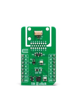
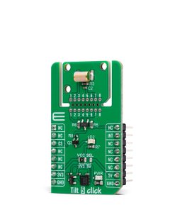
Tilt 5 Click is a compact add-on board for precise tilt detection in various motion-based applications. This board features the RBS240100T, a ball-contact tilt sensor switch from OncQue, capable of detecting a 45° tilt within a full 360° radius. The sensor operates in a normally open switch state, ensuring low power consumption while offering a contact resistance of 50mΩ, insulation resistance of 50MΩ, and a maximum contact current of 10mA. It uses a single INT pin for communication with the host MCU, providing a reliable tilt detection signal, while an onboard orange LD2 LED offers visual feedback. The board also supports the innovative Click Snap feature, allowing the sensor area to be detached for flexible integration. Tilt 5 Click is ideal for security systems, anti-theft and anti-tamper devices, alarm systems, earthquake detection units, and power-saving wake-up mechanisms.
Tilt 5 Click is fully compatible with the mikroBUS™ socket and can be used on any host system supporting the mikroBUS™ standard. It comes with the mikroSDK open-source libraries, offering unparalleled flexibility for evaluation and customization. What sets this Click board™ apart is the groundbreaking ClickID feature, enabling your host system to seamlessly and automatically detect and identify this add-on board, alongside a Click Snap feature introducing a new level of flexibility and ease of use.
Stock: Lead-time applicable.
| 5+ | R793.25 |
| 10+ | R751.50 |
| 15+ | R709.75 |
| 20+ | R683.03 |
How does it work?
Tilt 5 Click is based on the RBS240100T, a ball-contact tilt sensor switch from OncQue designed to provide precise tilt detection in various applications. This Click board™ uses the capabilities of the RBS240100T sensor, which reliably detects a 45° tilt within a full 360° radius, making it a highly versatile solution for motion-based triggering and orientation sensing. The sensor operates in a normally open switch state, ensuring low power consumption until a tilt event is detected. It offers exceptional electrical performance and reliability with a contact resistance of just 50mΩ and an insulation resistance of 50MΩ. The RBS240100T can also handle a maximum contact current of 10mA, making it suitable for a wide range of low-power and energy-efficient applications.

This Click board™ is ideal for security and safety systems, such as anti-theft and anti-tamper devices, where detecting unauthorized movement is crucial. It is also well-suited for alarm systems, earthquake detection units, and wake-up mechanisms designed to optimize power consumption by activating only when movement is detected.
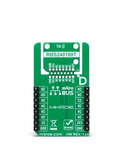
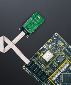
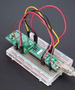
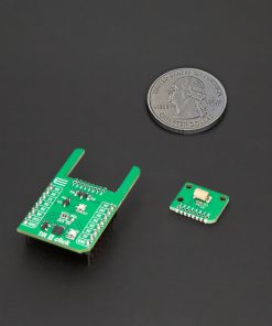
This Click board™ is designed in a unique format supporting the newly introduced MIKROE feature called “Click Snap.” Unlike the standardized version of Click boards, this feature allows the main sensor area to become movable by breaking the PCB, opening up many new possibilities for implementation. Thanks to the Snap feature, the RBS240100T can operate autonomously by accessing its signals directly on the pins marked 1-8. Additionally, the Snap part includes a specified and fixed screw hole position, enabling users to secure the Snap board in their desired location.
Tilt 5 Click uses a single INT pin as its primary connection to the host MCU, serving as the tilt detection signal. When a tilt event is detected, the sensor generates a signal through the INT pin, which is then processed by the host MCU for further action. In addition to the INT pin, the board features an orange LD2 LED that visually indicates tilt detection, ensuring real-time feedback for users and enhancing its practicality in various applications.
This Click board™ can operate with either 3.3V or 5V logic voltage levels selected via the VCC SEL jumper. This way, both 3.3V and 5V capable MCUs can use the communication lines properly. Also, this Click board™ comes equipped with a library containing easy-to-use functions and an example code that can be used as a reference for further development.
Click Snap
Click Snap is an innovative feature of our standardized Click add-on boards, introducing a new level of flexibility and ease of use. This feature allows for easy detachment of the main sensor area by simply snapping the PCB along designated lines, enabling various implementation possibilities. For detailed information about Click Snap, please visit the official page dedicated to this feature.
Specifications
Type
Motion
Applications
Ideal for security systems, anti-theft and anti-tamper devices, alarm systems, earthquake detection units, and power-saving wake-up mechanisms
On-board modules
RBS240100T – ball-contact tilt sensor switch from OncQue
Key Features
Detects a 45° tilt within a 360° radius, normally open switch state for low power consumption, 50mΩ contact resistance, 50MΩ insulation resistance, maximum contact current: 10mA, LED for visual tilt detection feedback, Click Snap feature, and more
Interface
GPIO
Feature
Click Snap,ClickID
Compatibility
mikroBUS™
Click board size
M (42.9 x 25.4 mm)
Input Voltage
3.3V or 5V
Pinout diagram
This table shows how the pinout on Tilt 5 Click corresponds to the pinout on the mikroBUS™ socket (the latter shown in the two middle columns).
| Notes | Pin | Pin | Notes | ||||
|---|---|---|---|---|---|---|---|
| NC | 1 | AN | PWM | 16 | NC | ||
| NC | 2 | RST | INT | 15 | INT | Tilt Detection | |
| ID COMM | CS | 3 | CS | RX | 14 | NC | |
| NC | 4 | SCK | TX | 13 | NC | ||
| NC | 5 | MISO | SCL | 12 | NC | ||
| NC | 6 | MOSI | SDA | 11 | NC | ||
| Power Supply | 3.3V | 7 | 3.3V | 5V | 10 | 5V | Power Supply |
| Ground | GND | 8 | GND | GND | 9 | GND | Ground |
Onboard settings and indicators
| Label | Name | Default | Description |
|---|---|---|---|
| LD1 | PWR | – | Power LED Indicator |
| LD2 | LD2 | – | Tilt Detection LED Indicator |
| JP1 | VCC SEL | Left | Power Voltage Level Selection 3V3/5V: Left position 3V3, Right position 5V |
Tilt 5 Click electrical specifications
| Description | Min | Typ | Max | Unit |
|---|---|---|---|---|
| Supply Voltage | 3.3 | – | 5 | V |
| Tilt Angle | – | – | 45 | deg |
Software Support
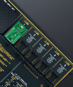
Tilt 5 Click demo application is developed using the NECTO Studio, ensuring compatibility with mikroSDK‘s open-source libraries and tools. Designed for plug-and-play implementation and testing, the demo is fully compatible with all development, starter, and mikromedia boards featuring a mikroBUS™ socket.
Example Description
This example demonstrates the use of the Tilt 5 Click board, which detects tilt motion using a ball switch sensor. The example initializes the device and continuously monitors the tilt state, logging changes between active and idle states.
Key Functions
tilt5_cfg_setupThis function initializes Click configuration structure to initial values.tilt5_initThis function initializes all necessary pins and peripherals used for this Click board.tilt5_get_out_pinThis function returns the OUT pin logic state.
Application Init
Initializes the logger and configures the Tilt 5 Click board.
Application Task
Continuously reads the tilt state and logs changes. The state toggles between “ACTIVE” when a tilt is detected and “IDLE” when the sensor is in its default position.
Application Output
This Click board can be interfaced and monitored in two ways:
- Application Output – Use the “Application Output” window in Debug mode for real-time data monitoring. Set it up properly by following this tutorial.
- UART Terminal – Monitor data via the UART Terminal using a USB to UART converter. For detailed instructions, check out this tutorial.
Additional Notes and Information
The complete application code and a ready-to-use project are available through the NECTO Studio Package Manager for direct installation in the NECTO Studio. The application code can also be found on the MIKROE GitHub account.
Resources
Downloads
| Weight | 17 g |
|---|---|
| Brand | MikroElektronika |