How does it work?
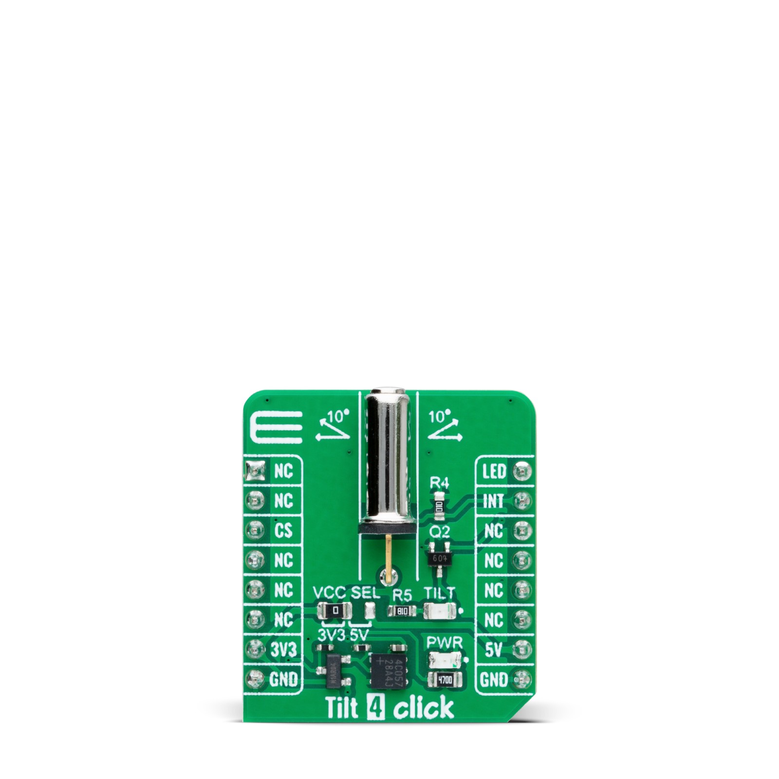
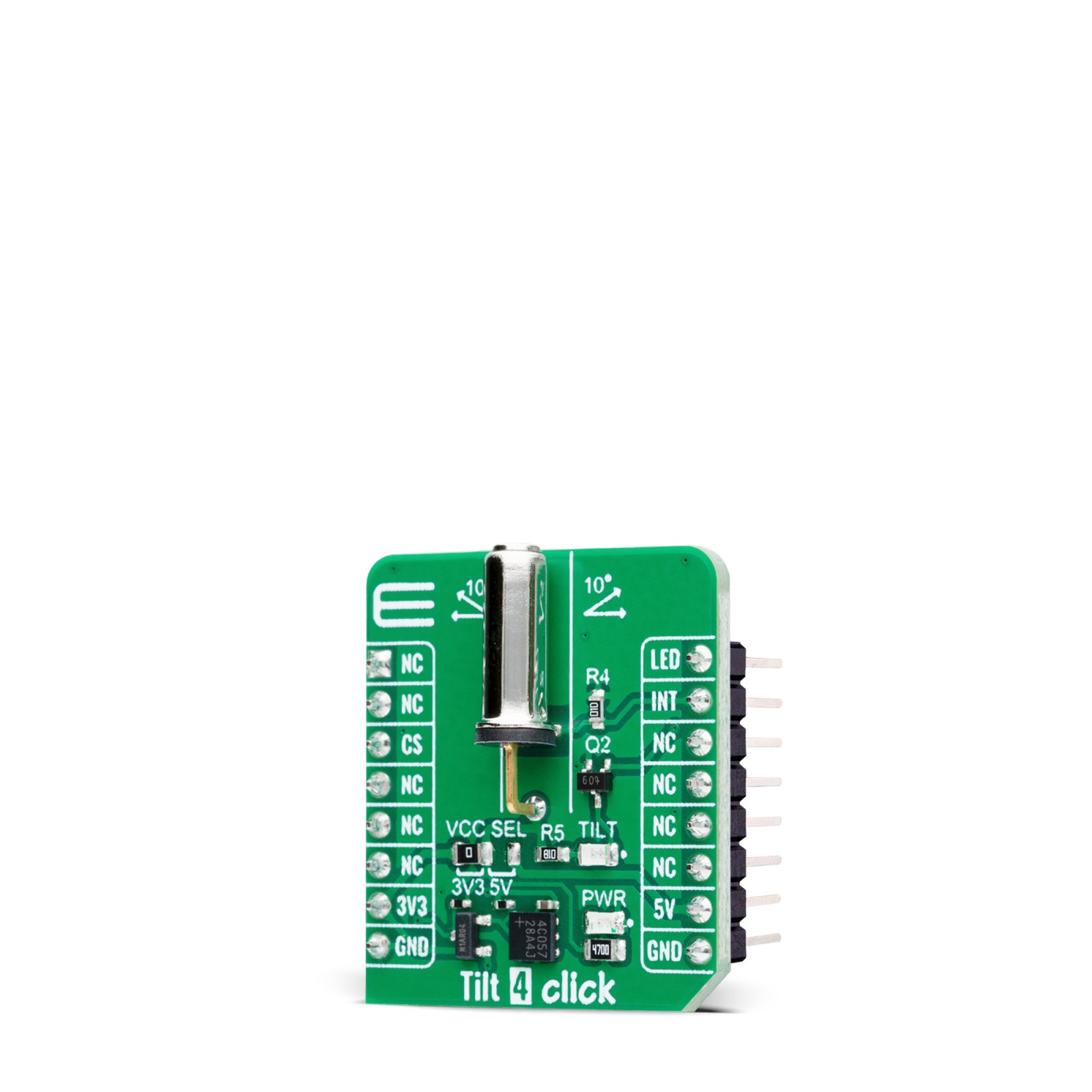
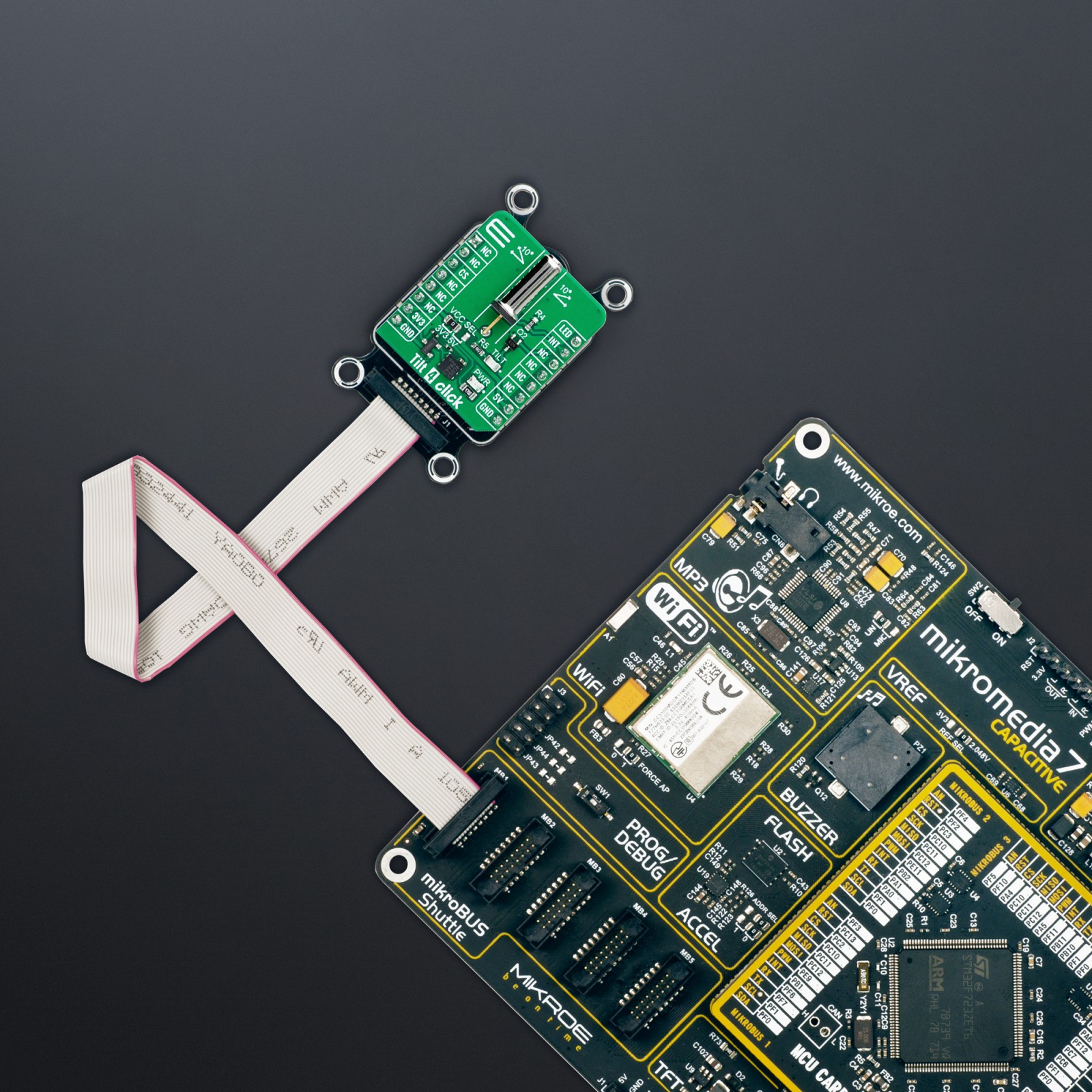
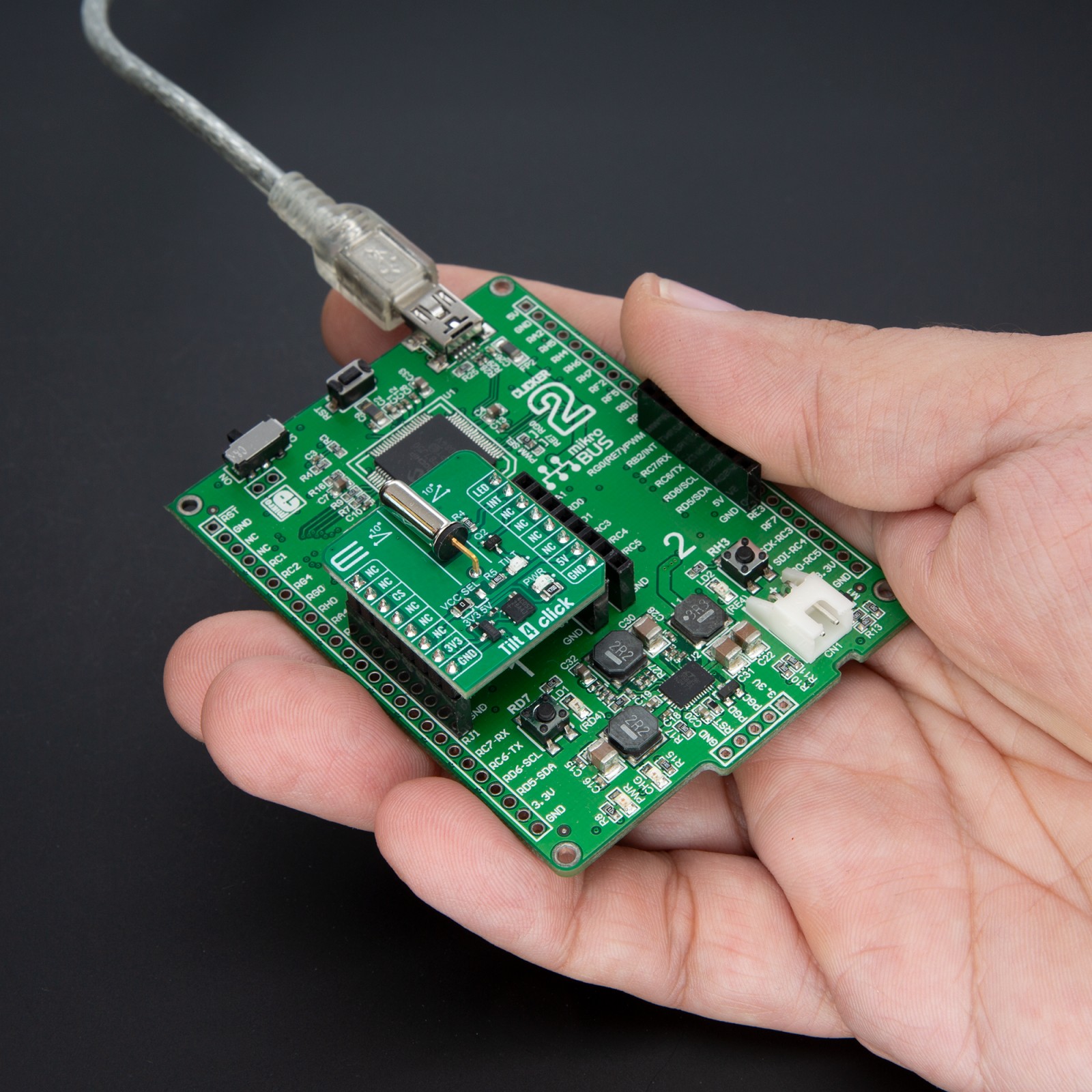
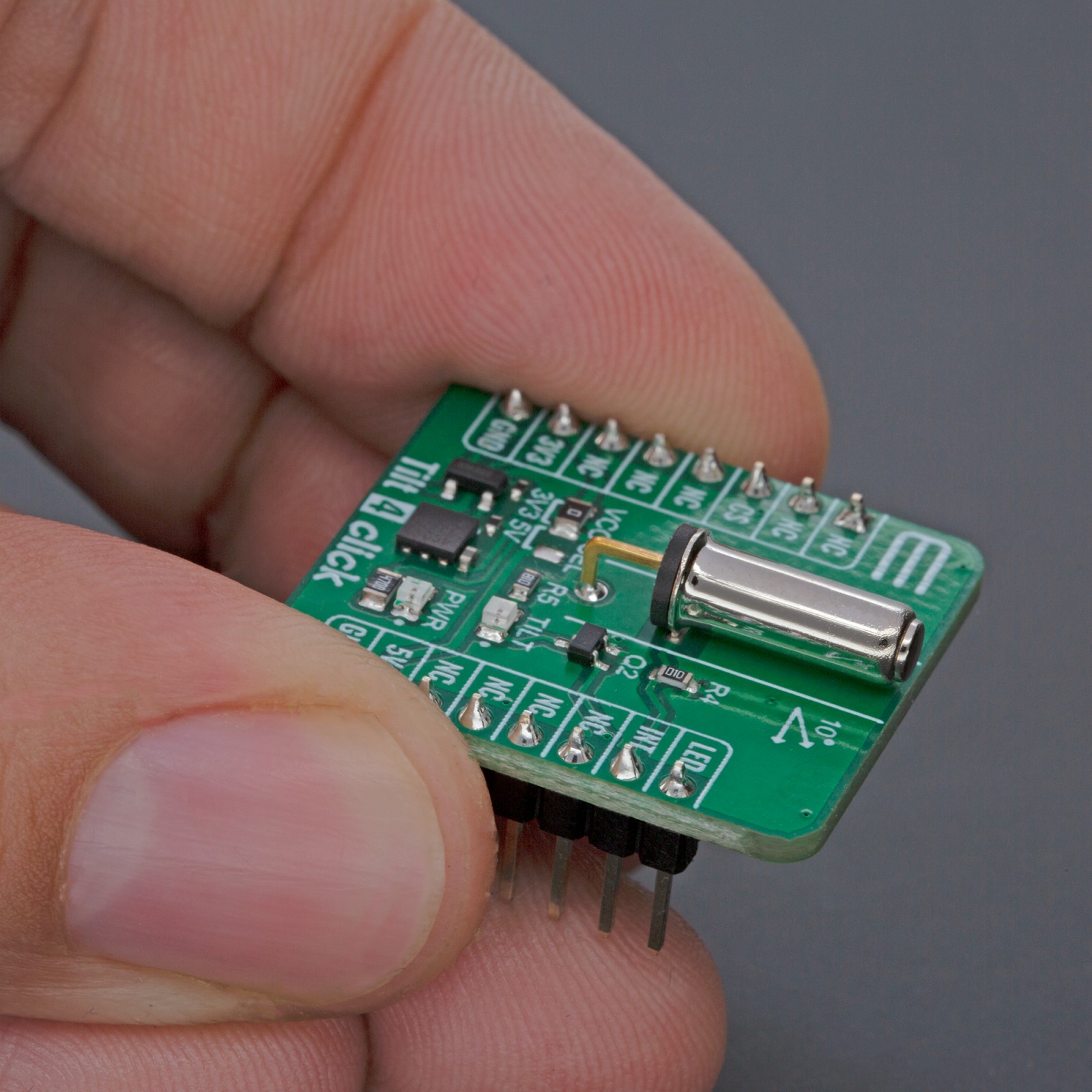
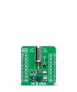
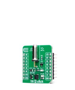
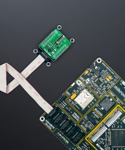
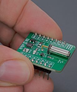
Tilt 4 Click is based on the RB-231X2, a rolling ball tilt switch from C&K Switches (Littelfuse) specially designed for safety control. This switch features a compact, shielded design that allows an angle of detection up to 10°. The conductive ball inside the tube moves to generate the signal and contact. The RB-231X2 offers an impressive operating life of 100,000 cycles, with key specifications including a single-pole single-throw (SPST) contact arrangement, a sensor angle range from 0˚ to 10˚, and dimensions of 9.7 mm in height, 16.6 mm in length, and 5.0 mm in width. It is ideal for movement detection, safety devices, white goods, and consumer electronic applications.
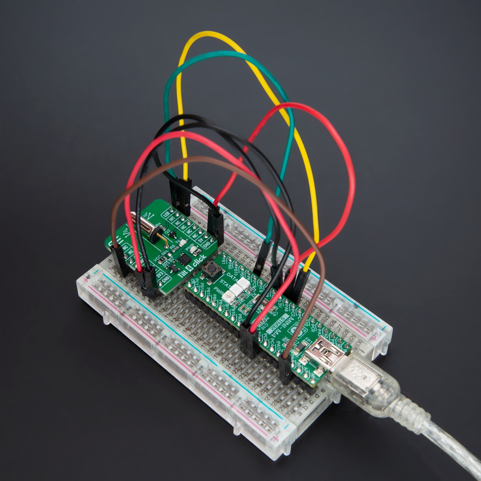
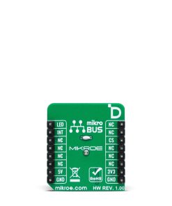
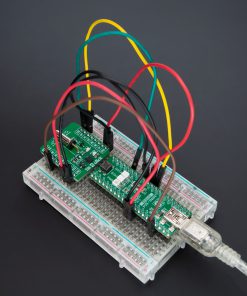
Tilt 4 Click interfaces with the MCU using only two pins: INT and LED pins of the mikroBUS™ socket. The INT pin is an interrupt signal, immediately alerting the MCU upon detecting a tilt event, ensuring prompt response and processing. Meanwhile, the LED pin controls the TILT red LED, which provides a clear visual indication whenever a tilt is detected. This dual-pin configuration simplifies the connection process and enhances the efficiency and reliability of tilt detection and indication. The INT pin’s role in delivering real-time interrupt signals is crucial for applications requiring immediate action, while the LED pin’s control over the TILT red LED ensures that the status of the tilt detection is always visible, making it easier to monitor and debug.
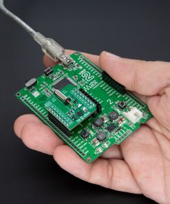
This Click board™ can operate with either 3.3V or 5V logic voltage levels selected via the VCC SEL jumper. This way, both 3.3V and 5V capable MCUs can use the communication lines properly. Also, this Click board™ comes equipped with a library containing easy-to-use functions and an example code that can be used as a reference for further development.
Specifications
Type
Motion
Applications
Ideal for movement detection, safety devices, white goods, and consumer electronics
On-board modules
RB-231X2 – rolling ball tilt switch from C&K Switches (Littelfuse)
Key Features
High-quality rolling ball tilt switch, compact and shielded design, detection angle up to 10°, operating life of 100,000 cycles, interrupt signal and LED for visual tilt indication, supports both 3.3V and 5V logic levels, and more
Interface
GPIO
Feature
ClickID
Compatibility
mikroBUS™
Click board size
S (28.6 x 25.4 mm)
Input Voltage
3.3V or 5V
Pinout diagram
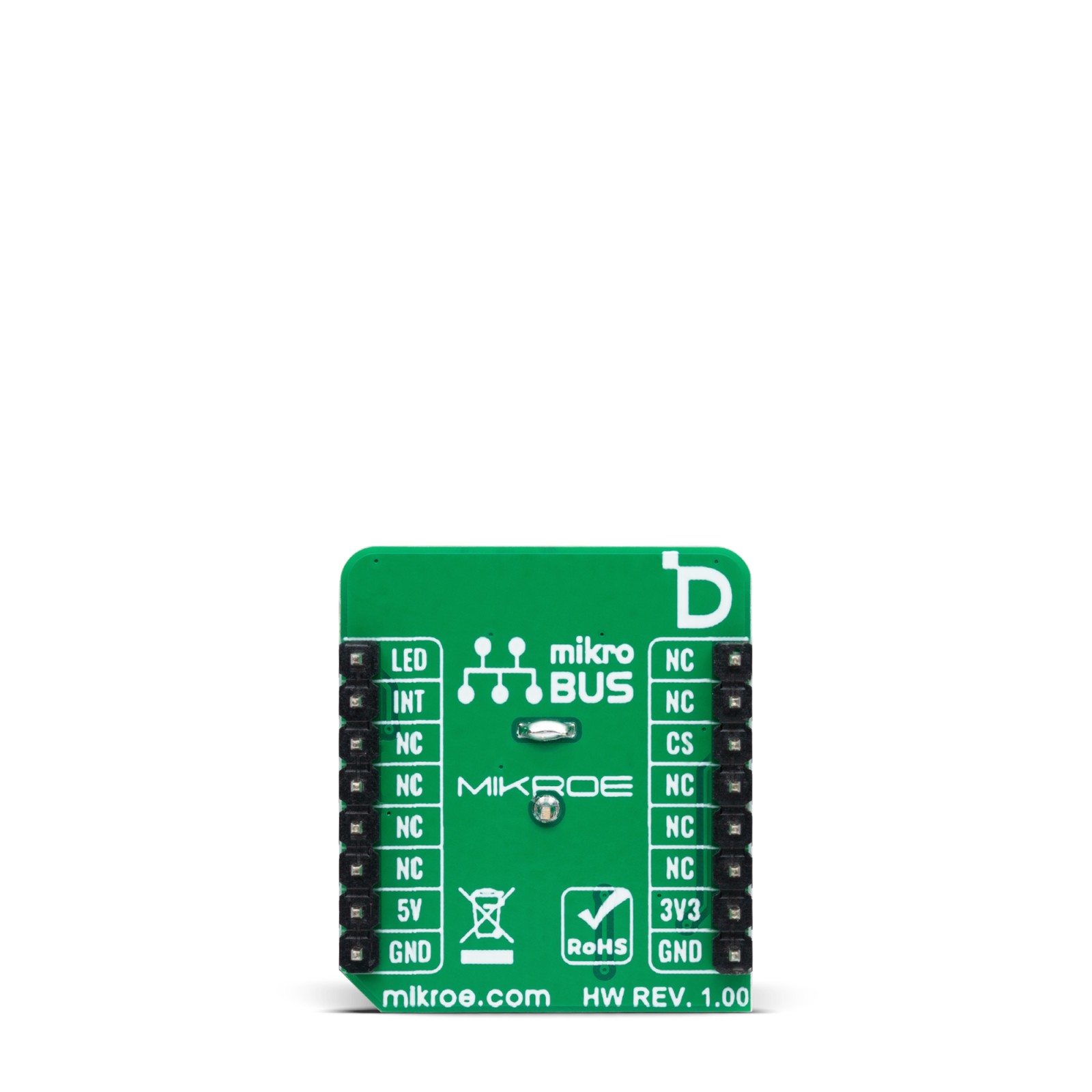
This table shows how the pinout on Tilt 4 Click corresponds to the pinout on the mikroBUS™ socket (the latter shown in the two middle columns).
Onboard settings and indicators
Label | Name | Default | Description |
---|---|---|---|
LD1 | PWR | – | Power LED Indicator |
LD2 | TILT | – | Tilt Detection LED Indicator |
JP1 | VCC SEL | Left | Power Voltage Level Selection 3V3/5V: Left position 3V3, Right position 5V |
Tilt 4 Click electrical specifications
Description | Min | Typ | Max | Unit |
---|---|---|---|---|
Supply Voltage | 3.3 | – | 5 | V |
Tilt Detection Angle | 0 | – | 10 | deg |
Software Support
We provide a library for the Tilt 4 Click as well as a demo application (example), developed using MIKROE compilers. The demo can run on all the main MIKROE development boards.
Package can be downloaded/installed directly from NECTO Studio Package Manager (recommended), downloaded from our LibStock™ or found on MIKROE github account.
Library Description
This library contains API for Tilt 4 Click driver.
Key functions
-
tilt4_read_int_state
This function reads the state of the interrupt pin of Tilt 4 click board. -
tilt4_set_led_state
This function sets the LED pin on the selected level level of Tilt 4 click board.
Example Description
This example demonstrates the use of Tilt 4 Click board™.
void application_task ( void )
{
uint8_t state = tilt4_read_int_state ( &tilt4 );
if ( tilt4_switch_state != state )
{
tilt4_switch_state = state;
if ( TILT4_SWITCH_ON == tilt4_switch_state )
{
log_printf( &logger, " Tilt switch ON!rnn" );
tilt4_set_led_state( &tilt4, TILT4_PIN_STATE_HIGH );
}
else
{
log_printf( &logger, " Tilt switch OFF!rnn" );
tilt4_set_led_state( &tilt4, TILT4_PIN_STATE_LOW );
}
Delay_ms( 500 );
}
}
The full application code, and ready to use projects can be installed directly from NECTO Studio Package Manager(recommended), downloaded from our LibStock™ or found on MIKROE github account.
Other MIKROE Libraries used in the example:
- MikroSDK.Board
- MikroSDK.Log
- Click.Tilt4
Additional notes and informations
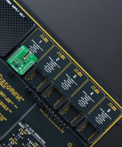
Depending on the development board you are using, you may need USB UART click, USB UART 2 Click or RS232 Click to connect to your PC, for development systems with no UART to USB interface available on the board. UART terminal is available in all MIKROE compilers.
mikroSDK
This Click board™ is supported with mikroSDK – MIKROE Software Development Kit. To ensure proper operation of mikroSDK compliant Click board™ demo applications, mikroSDK should be downloaded from the LibStock and installed for the compiler you are using.
For more information about mikroSDK, visit the official page.