How does it work?
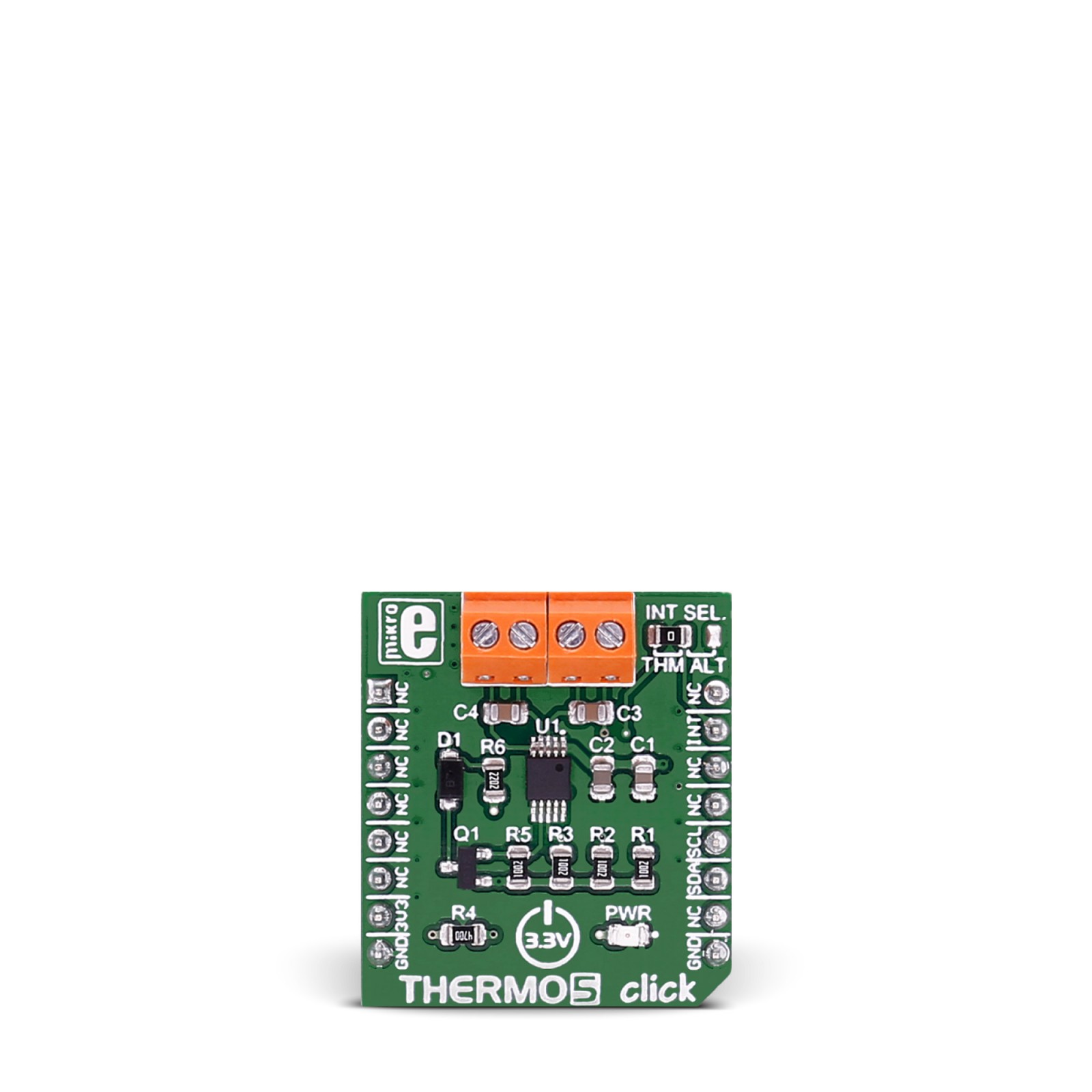
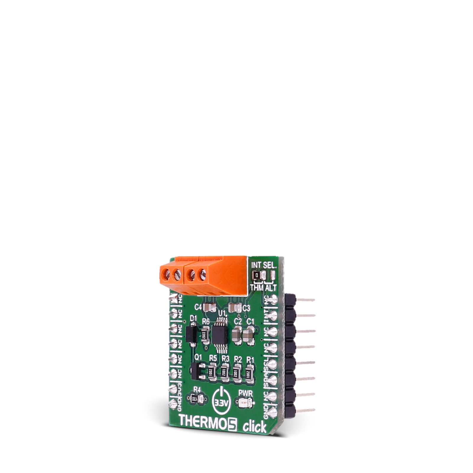
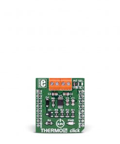
Thermo 5 Click is based on the EMC1414, a multiple-channel temperature sensor with beta compensation from Microchip. It features resistance error correction (REC), beta compensation that supports CPU diodes requiring the BJT/transistor models, and, above all, an automatic diode-type detection, which provides a robust solution for complex environmental monitoring applications. The device contains programmable High, Low, and Thermo limits for all measured temperature channels. If the measured temperature goes below the Low limit or above the High limit, the ALERT pin can be asserted (based on user settings). If the measured temperature meets or exceeds the Thermo Limit, the output pin is asserted unconditionally, providing two tiers of temperature detection.
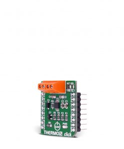
Thermo 5 Click uses a 2-Wire SMBus communication protocol to communicate with the host MCU. It has a programmable SMBus address. By setting the INT SEL jumper, you can choose the interrupts from the THM and ALT, which stands for Therm and Alert (the THM is set by default). This way, the output is asserted whenever the measured temperatures exceed programmed limits. The Alert mode has an interrupt and a comparator mode of operation. The interrupt mode asserts the output if there is a faulty diode or an out-of-limit measurement is detected. The output pin will be asserted in comparator mode if the measured temperatures exceed the respective high limit.
This Click board™ can be operated only with a 3.3V logic voltage level. The board must perform appropriate logic voltage level conversion before using MCUs with different logic levels. However, the Click board™ comes equipped with a library containing functions and an example code that can be used as a reference for further development.
Specifications
Type
Temperature & humidity
Applications
Can be used for developing notebook computers, desktop computers, industrial applications, embedded applications, and more
On-board modules
EMC1414 – multiple-channel temperature sensor with beta compensation from Microchip
Key Features
Programmable SMBus address, support, or diodes requiring the BJT/transistor model, automatically determine external diode type and optimal settings, resistance error correction, internal temperature monitor, programmable temperature limits, and more
Interface
I2C
Feature
No ClickID
Compatibility
mikroBUS™
Click board size
S (28.6 x 25.4 mm)
Input Voltage
3.3V
Pinout diagram
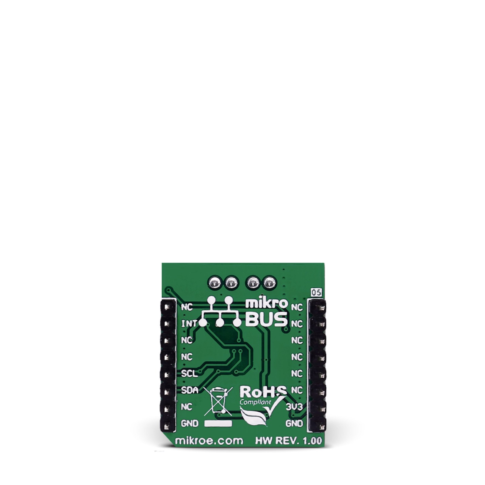
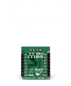
This table shows how the pinout on THERMO 5 Click corresponds to the pinout on the mikroBUS™ socket (the latter shown in the two middle columns).
Onboard settings and indicators
Label | Name | Default | Description |
---|---|---|---|
– | PWR | – | Power LED Indicator |
– | INT SEL | Left | Interrupt Output Selection THM/ALT: Left position THM, Right position ALT |
THERMO 5 Click electrical specifications
Description | Min | Typ | Max | Unit |
---|---|---|---|---|
Supply Voltage | – | 3.3 | – | V |
Default Operating Temperature Range | 0 | – | 127 | °C |
Temperature Accuracy | – | 1 | – | °C |
Temperature Resolution | – | 0.125 | – | °C |
Software Support
We provide a library for the THERMO 5 Click as well as a demo application (example), developed using MIKROE compilers. The demo can run on all the main MIKROE development boards.
Package can be downloaded/installed directly from NECTO Studio Package Manager(recommended), downloaded from our LibStock™ or found on Mikroe github account.
Library Description
This library contains API for THERMO 5 Click driver.
Key functions
-
This function reads measurements made by internal diode.
-
This function reads measurements made by external 1 diode.
-
This function reads the High Limit Status register which utilises its lower nibble to represents which diodes have exceed their programmed high limit.
Example Description
This app measures internal and external temperature.
void application_task ( void )
{
float inter_temp;
float exter_temp_1;
float exter_temp_2;
float exter_temp_3;
inter_temp = thermo5_read_inter_temp( &thermo5 );
log_printf( &logger, " Internal temperature : %.2f rn", inter_temp );
exter_temp_1 = thermo5_read_extern_1_temp( &thermo5 );
log_printf( &logger, " External temperature 1 : %.2f rn", exter_temp_1 );
exter_temp_2 = thermo5_read_extern_2_temp( &thermo5 );
log_printf( &logger, " External temperature 2 : %.2f rn", exter_temp_2 );
exter_temp_3 = thermo5_read_extern_3_temp( &thermo5 );
log_printf( &logger, " External temperature 3 : %.2f rn", exter_temp_2 );
log_printf( &logger, "---------------------------------rn" );
Delay_ms ( 1000 );
Delay_ms ( 1000 );
Delay_ms ( 1000 );
Delay_ms ( 1000 );
Delay_ms ( 1000 );
}
The full application code, and ready to use projects can be installed directly from NECTO Studio Package Manager(recommended), downloaded from our LibStock™ or found on Mikroe github account.
Other Mikroe Libraries used in the example:
- MikroSDK.Board
- MikroSDK.Log
- Click.THERMO5
Additional notes and informations
Depending on the development board you are using, you may need USB UART click, USB UART 2 Click or RS232 Click to connect to your PC, for development systems with no UART to USB interface available on the board. UART terminal is available in all MIKROE compilers.
mikroSDK
This Click board™ is supported with mikroSDK – MIKROE Software Development Kit. To ensure proper operation of mikroSDK compliant Click board™ demo applications, mikroSDK should be downloaded from the LibStock and installed for the compiler you are using.
For more information about mikroSDK, visit the official page.