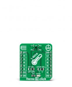
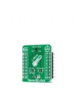
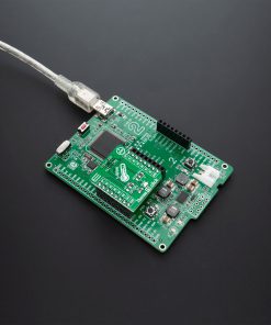
Thermo 19 Click
R335.00 ex. VAT
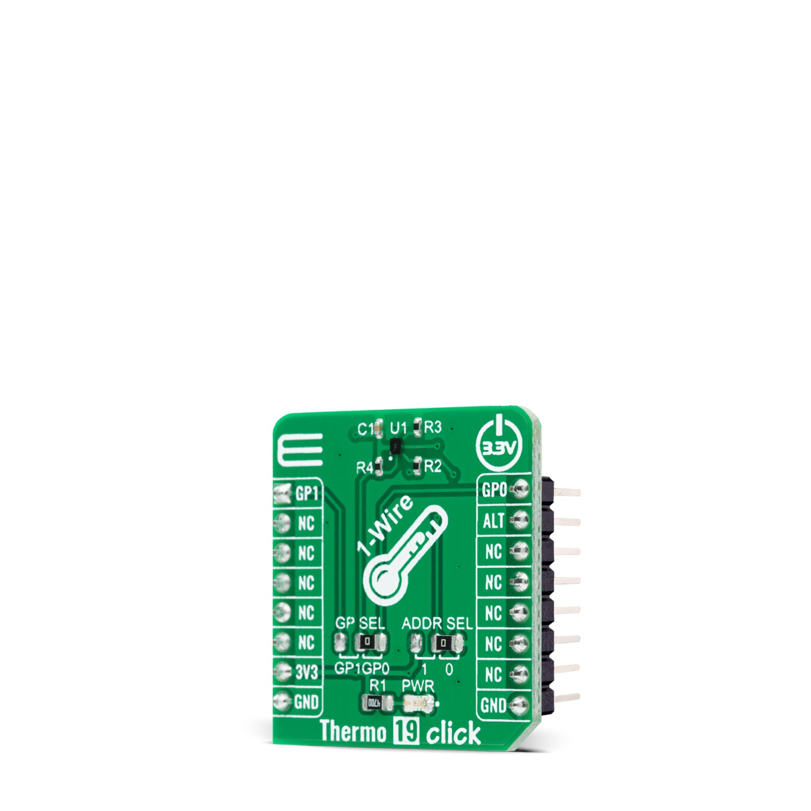
Thermo 19 Click is a compact add-on board that provides an accurate temperature measurement. This board features the MAX31825, a temperature sensor that provides 8-bit to 12-bit Celsius temperature measurements with better than ±1.75°C from -45°C to +145°C from Analog Devices. It has a unique 64-bit serial code stored in an on-chip ROM, an alarm output for detection of temperature faults, temperature resolution selection from 8 to 12 bits, and it allows temperature conversion to 10-bit digital word in a period of 80ms (max). This Click board™ makes a perfect choice for industrial control, in communication and data center equipment, or in any other temperature measurement applications.
Thermo 19 Click is supported by a mikroSDK compliant library, which includes functions that simplify software development. This Click board™ comes as a fully tested product, ready to be used on a system equipped with the mikroBUS™ socket.
Stock: Lead-time applicable.
| 5+ | R318.25 |
| 10+ | R301.50 |
| 15+ | R284.75 |
| 20+ | R274.03 |
How does it work?
Thermo 19 Click is based on the MAX31825, a digital thermometer that provides 12-bit temperature measurements and communicates over a 1-Wire interface from Analog Devices. The sensor provides 8-bit to 12-bit temperature measurements from -45°C to +145°C with better that ±1.75°C accuracy, and better than ±1°C accuracy from 0°C to +70°C. Temperature measurements are sent to the MCU using the 1-Wire interface that requires only one data line that can also be used to parasitically power the sensor. Besides, it includes two address input pins that allow one of 64 different addresses to be selected to identify the sensor’s physical location, and an interrupt that represents an alarm output for detection of temperature measurement faults.
.jpg)
The transaction sequence for accessing the device MAX31825 through the 1-Wire interface consists of additional steps:
- Initialization sequence – It consists of a reset pulse transmitted by the MCU followed by the presence pulse transmitted by the MAX31825, which gives the MCU information that the MAX31825 is on the bus and is ready to operate.
- ROM Command – Once the MCU has detected a presence, it can issue one of the four 8-bit long ROM commands that the MAX31825 support.
- Function Command – Commands that allows the MCU to read from the MAX31825 scratchpad memory, and initiate temperature conversions.
- Transaction/Data – The idle state for the 1-Wire bus is high. If for any reason a transaction needs to be suspended, the bus MUST be left in the idle state if the transaction is to resume. Infinite recovery time can occur between bits so long as the 1-Wire bus is in the inactive (high) state during the recovery period. If the bus is held low for more than 480μs, all components on the bus are reset.
NOTE: It is very important to follow this sequence every time the MAX31825 is accessed, as the MAX31825 does not respond if any steps in the sequence are missing or out of order.
The Thermo 19 Click communicates with MCU using the 1-Wire interface that, by definition, requires only one data line (and ground) for communication with MCU. The 1-Wire communication line is routed to the SMD jumper labeled as GP SEL, which allows routing of the 1-Wire communication either to the PWM pin or to the AN pin of the mikroBUS™ socket. These pins are labeled as GP0 and GP1 respectively, the same as the SMD jumper positions, making the selection of the desired pin simple and straightforward.
The MAX31825 possesses an interrupt output that represents alarm output with user-definable settings for temperature fault detection routed to the INT pin on the mikroBUS™ socket, labeled as ALT. It also includes two address pins (ADD0 and ADD1). ADD0 is connected to an external resistor whose value is measured by the MAX31825 in response to the Convert Location command, resulting in five location address bits (A4:A0) stored in the Status register. In addition to ADD0, the ADD1 input can be connected to GND or VDD, labeled as 0 and 1, which can be performed by using the SMD jumper labeled as ADDR SEL.
This Click board™ is designed to be operated only with a 3.3V logic voltage level. A proper logic voltage level conversion should be performed before the Click board™ is used with MCUs with different logic levels.
Specifications
Type
Temperature & humidity
Applications
Can be used for industrial control, in communication and data center equipment, or in any other temperature measurement applications.
On-board modules
Thermo 19 Click is based on the MAX31825, a digital thermometer that provides 12-bit temperature measurements and communicates over a 1-Wire interface from Maxim Integrated.
Key Features
Better accuracy, alarm function for detection of temperature faults, selectable temperature resolution, wide temperature measurement range, can be powered from the data line, and more.
Interface
1-Wire
Feature
No ClickID
Compatibility
mikroBUS™
Click board size
S (28.6 x 25.4 mm)
Input Voltage
3.3V
Pinout diagram
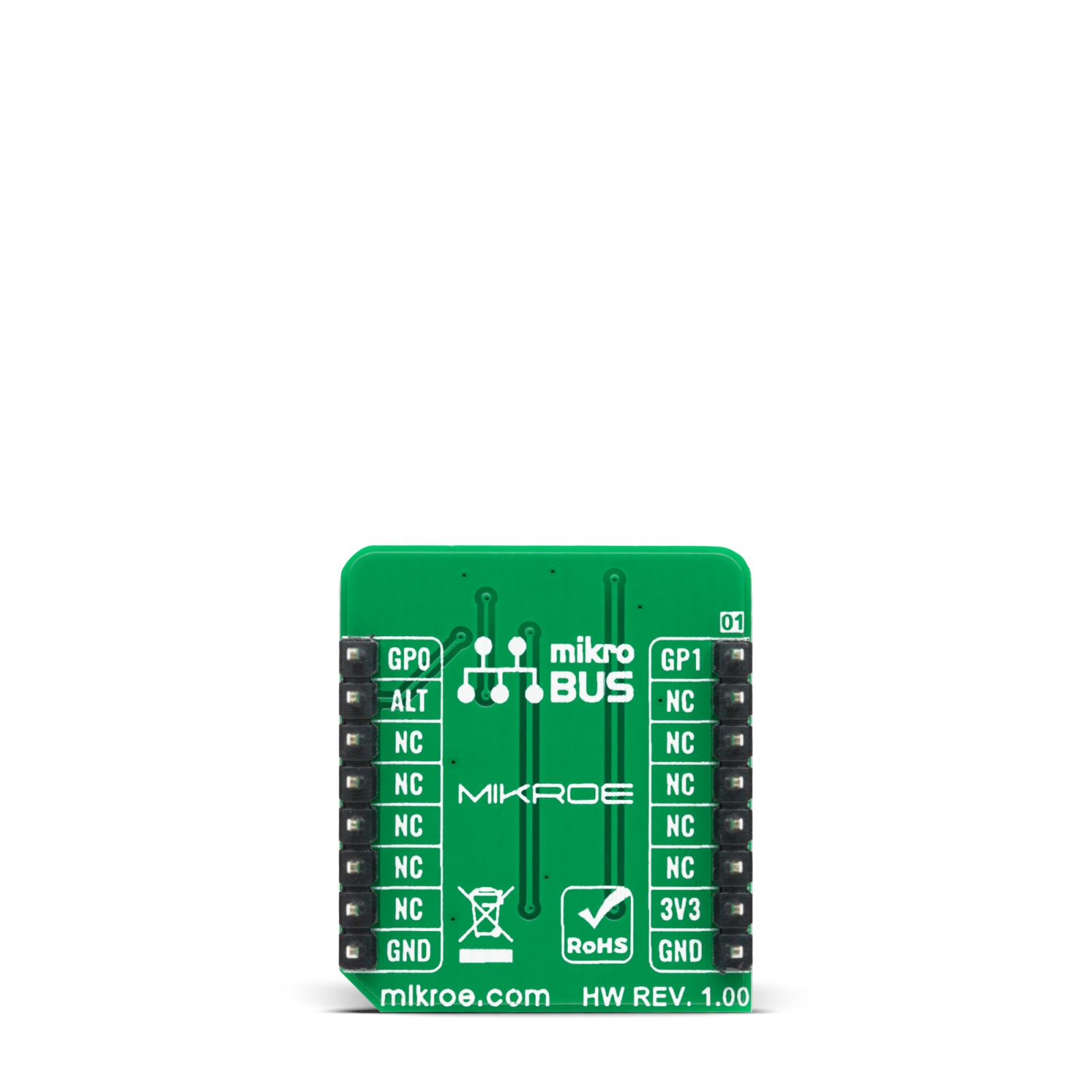
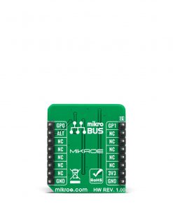
This table shows how the pinout on Thermo 19 Click corresponds to the pinout on the mikroBUS™ socket (the latter shown in the two middle columns).
Onboard settings and indicators
| Label | Name | Default | Description |
|---|---|---|---|
| LD1 | PWR | – | Power LED Indicator |
| JP1 | GP SEL | Right | Communication Pin Selection GP1/GP0: Left position GP1, Right position GP0 |
| JP2 | ADDR SEL | Right | Location Address Selection 1/0: Left position 1, Right position 0 |
Thermo 19 Click electrical specifications
| Description | Min | Typ | Max | Unit |
|---|---|---|---|---|
| Supply Voltage | -0.3 | 3.3 | 4 | V |
| Temperature Measurement Error | -1.75 | ±0.3 | 1.75 | °C |
| Temperature Resolution | 8 | – | 12 | bits |
| Operating Temperature Range | -45 | – | +145 | °C |
Software Support
We provide a library for the Thermo 19 Click on our LibStock page, as well as a demo application (example), developed using MikroElektronika compilers. The demo can run on all the main MikroElektronika development boards.
Library Description
Library holds function that chechs the state of the “Alarm” pin.
Key functions:
uint8_t thermo19_alarm_chk ( );– Function is used to check if an Alarm has occured.
Examples description
The application is composed of three sections :
- System Initialization – Initializes GPIO and LOG structures , and sets INT pin as input.
- Application Initialization – Initalizes GPIO driver, applies default settings via one wire communication and start to write log.
- Application Task – This example shows capabilities of Thermo 19 click by measuring temperature and displaying temperature in degrees Celsius via USART terminal.
void application_task ( )
{
    temperature = thermo19_get_temperature( );
    FloatToStr( temperature, log_txt );
    Ltrim( log_txt );
    mikrobus_logWrite( " Temperature : ", _LOG_TEXT );
    mikrobus_logWrite( log_txt, _LOG_TEXT );
    mikrobus_logWrite( deg_cel, _LOG_LINE );
}
Additional Functions :
- void thermo19_one_wire_init ( ) – Function initialises one wire communication.
- void thermo19_rom_skip ( ) – Function sends skip ROM command.
- float thermo19_get_temperature ( ) – Functions reads, calculates and returns temperature, and the device’s status.
- void thermo19_dev_setup ( uint8_t dev_cfg, float trsh_h, float trsh_l ) – Functions sets up the configuration (uint8_t dev_cfg) and high (float trsh_h) and low (float trsh_l) alarm thresholds.
The full application code, and ready to use projects can be found on our LibStock page.
Other mikroE Libraries used in the example:
- One Wire
- UART
- Conversions
Additional notes and informations
Depending on the development board you are using, you may need USB UART click, USB UART 2 click or RS232 click to connect to your PC, for development systems with no UART to USB interface available on the board. The terminal available in all MikroElektronika compilers, or any other terminal application of your choice, can be used to read the message.
mikroSDK
This Click board™ is supported with mikroSDK – MikroElektronika Software Development Kit. To ensure proper operation of mikroSDK compliant Click board™ demo applications, mikroSDK should be downloaded from the LibStock and installed for the compiler you are using.
For more information about mikroSDK, visit the official page.
Resources
Downloads
| Weight | 17 g |
|---|---|
| Brand | MikroElektronika |


