
Tester 2 Click
R220.00 ex. VAT
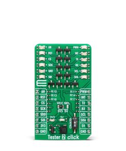
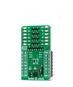
Tester 2 Click is a diagnostic Click board™ designed for real-time visual monitoring of mikroBUS™ pin logic levels. It features a 2×6 LED array controlled by SI2310 N-channel MOSFETs, providing reliable feedback on pin states and additional LEDs for monitoring the activity of +3.3V and +5V power rails. The board also includes a ClickID switch for using the CS pin as a ClickID signal, and LP CUT traces for low-power operation by disabling LEDs and the ClickID section. Fully compatible with the mikroBUS™ standard, Tester 2 Click is easy to integrate and requires no additional configuration. It is ideal for debugging and troubleshooting embedded systems, saving developers time and effort.
Tester 2 Click is fully compatible with the mikroBUS™ socket and can be used on any host system supporting the mikroBUS™ standard. It comes with the mikroSDK open-source libraries, offering unparalleled flexibility for evaluation and customization. What sets this Click board™ apart is the groundbreaking ClickID feature, enabling your host system to seamlessly and automatically detect and identify this add-on board.
Stock: Lead-time applicable.
| 5+ | R209.00 |
| 10+ | R198.00 |
| 15+ | R187.00 |
| 20+ | R179.96 |
How does it work?
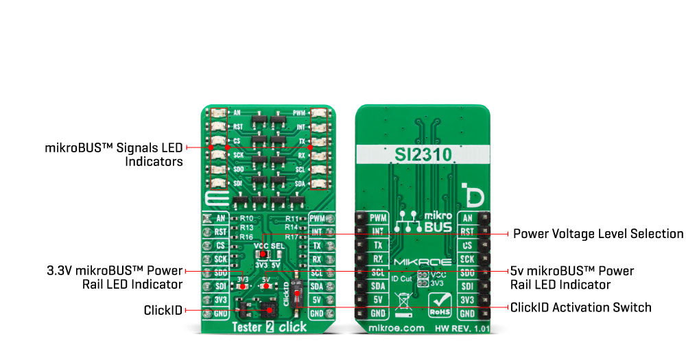
Tester 2 Click is a diagnostic Click board™ designed to provide immediate and reliable visual feedback on the logic levels of mikroBUS™ pins. It features a 2×6 array of orange LEDs, each connected to a specific mikroBUS™ pin, allowing developers to instantly determine whether the logic state on a pin is HIGH or LOW. For easy identification, each LED is clearly labeled with the name of the corresponding pin, such as PWM or AN. Additionally, the board includes two LEDs dedicated to monitoring the mikroBUS™ power rails, signaling the presence of +3.3V and +5V voltages. This functionality eliminates the need for additional diagnostic tools or complex measurement setups, saving developers valuable time and effort during debugging and troubleshooting.
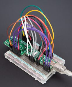
Using Tester 2 Click is straightforward. Once the board is inserted into the mikroBUS™ socket, it becomes fully operational without requiring additional configuration or setup. The power indication LEDs immediately signal the presence of voltage on the mikroBUS™ power rails, while the rest of the LED array lights up based on the logic states of their respective pins. The simplicity of the design, which uses LEDs and SI2310 N-channel MOSFETs for controlling their operation, ensures reliability and ease of use, making it an indispensable tool for developers working with mikroBUS™ systems.
The board is built to be fully compatible with the standardized mikroBUS™ connector, a key feature of MIKROE development systems. This connector ensures that all commonly used interfaces, including SPI, I2C, UART, PWM, analog input (AN), and various GPIO pins such as CS, INT, and RST, are consistently mapped across all platforms equipped with mikroBUS™ sockets. It also incorporates two power supply rails, +3.3V, and +5V, allowing compatibility between different systems and a wide range of Click boards™. This standardization means that Tester 2 Click can be used across various platforms without requiring hardware modifications, ensuring flexibility and ease of integration for developers.
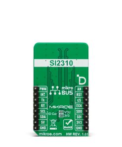
A notable addition to this board is a switch that activates the ClickID feature, allowing the signal from ClickID to be used on the CS pin instead of the standard SPI Chip Select functionality. Additionally, the board includes LP CUT traces on its backside, which are designed to support low-power operation. By severing these traces, the power supply to the LEDs and the ClickID section is disconnected, drastically reducing power consumption and enabling efficient operation, especially in applications where energy efficiency is critical.
This Click board™ can operate with either 3.3V or 5V logic voltage levels selected via the VCC SEL jumper. This way, both 3.3V and 5V capable MCUs can use the communication lines properly. Also, this Click board™ comes equipped with a library containing easy-to-use functions and an example code that can be used as a reference for further development.
Specifications
Type
Proto
Applications
Ideal for debugging and troubleshooting embedded systems, saving developers time and effort
On-board modules
None
Key Features
2×6 orange LEDs for visual feedback on mikroBUS™ pin logic levels, dedicated LEDs for +3.3V and +5V power rail monitoring, ClickID switch, low-power support, plug-and-play design, and more
Interface
Analog,GPIO,I2C,PWM,SPI,UART
Feature
ClickID
Compatibility
mikroBUS™
Click board size
M (42.9 x 25.4 mm)
Input Voltage
3.3V or 5V
Pinout diagram
This table shows how the pinout on Tester 2 Click corresponds to the pinout on the mikroBUS™ socket (the latter shown in the two middle columns).
| Notes | Pin | Pin | Notes | ||||
|---|---|---|---|---|---|---|---|
| Analog Output | AN | 1 | AN | PWM | 16 | PWM | PWM Input |
| Reset / ID SEL | RST | 2 | RST | INT | 15 | INT | Interrupt |
| SPI Select / ID COMM | CS | 3 | CS | RX | 14 | TX | UART TX |
| SPI Clock | SCK | 4 | SCK | TX | 13 | RX | UART RX |
| SPI Data OUT | SDO | 5 | MISO | SCL | 12 | SCL | I2C Clock |
| SPI Data IN | SDI | 6 | MOSI | SDA | 11 | SDA | I2C Data |
| Power Supply | 3.3V | 7 | 3.3V | 5V | 10 | 5V | Power Supply |
| Ground | GND | 8 | GND | GND | 9 | GND | Ground |
Onboard settings and indicators
| Label | Name | Default | Description |
|---|---|---|---|
| LD1-LD2 | – | – | Power LED Indicators |
| LD3-LD14 | – | – | mikroBUS™ Signals LED Indicators |
| JP1 | VCC SEL | Left | Power Voltage Level Selection 3V3/5V: Left position 3V3, Right position 5V |
| SW1 | ClickID | Upper | ClickID Activation Switch SPI CS/ClickID: Upper position SPI CS, Right position ClickID |
Tester 2 Click electrical specifications
| Description | Min | Typ | Max | Unit |
|---|---|---|---|---|
| Supply Voltage | 3.3 | – | 5 | V |
Software Support
Tester 2 Click demo application is developed using the NECTO Studio, ensuring compatibility with mikroSDK‘s open-source libraries and tools. Designed for plug-and-play implementation and testing, the demo is fully compatible with all development, starter, and mikromedia boards featuring a mikroBUS™ socket.
Example Description
This example demonstrates the use of Tester 2 Click board by controlling all LEDs on the Click board together and in sequential pin toggling with different delays.
Key Functions
tester2_cfg_setupConfig Object Initialization function.tester2_initInitialization function.tester2_toggle_allThis function toggles all mikroBUS pins together a desired number of times with the selected delay between each toggle.tester2_toggle_seqThis function toggles all mikroBUS pins one by one with the selected delay between each toggle.
Application Init
Initializes the driver and logger.
Application Task
Toggles all pins together 5 times with a 500ms delay between each toggle, then toggles each pin sequentially with a 300ms delay between toggling each pin.
Application Output
This Click board can be interfaced and monitored in two ways:
- Application Output – Use the “Application Output” window in Debug mode for real-time data monitoring. Set it up properly by following this tutorial.
- UART Terminal – Monitor data via the UART Terminal using a USB to UART converter. For detailed instructions, check out this tutorial.
Additional Notes and Information
The complete application code and a ready-to-use project are available through the NECTO Studio Package Manager for direct installation in the NECTO Studio. The application code can also be found on the MIKROE GitHub account.
Resources
Downloads
| Weight | 17 g |
|---|---|
| Brand | MikroElektronika |