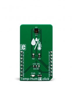
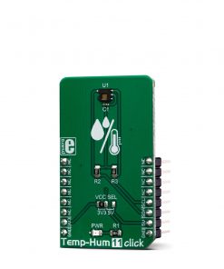
Temp&Hum 11 Click
R285.00 ex. VAT
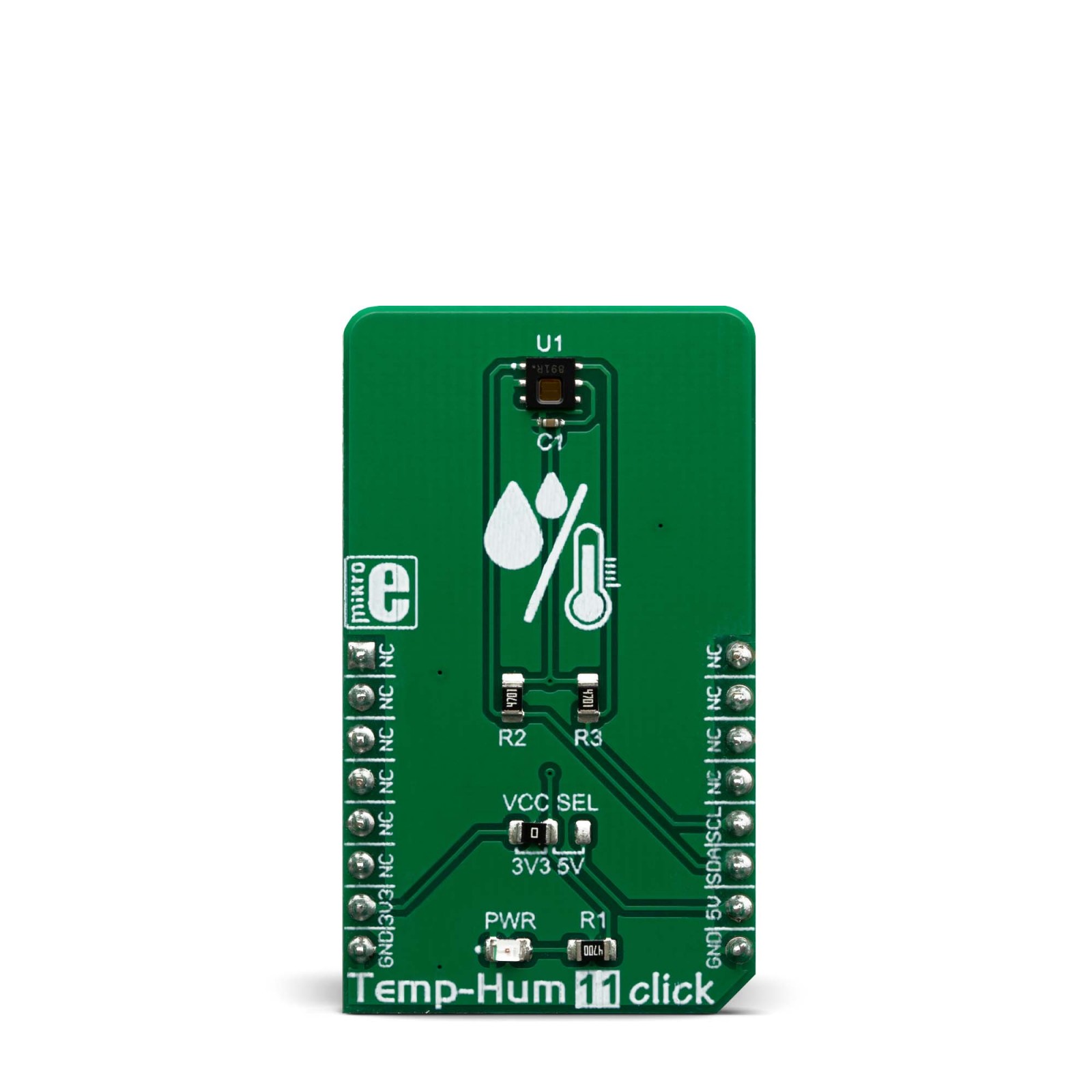
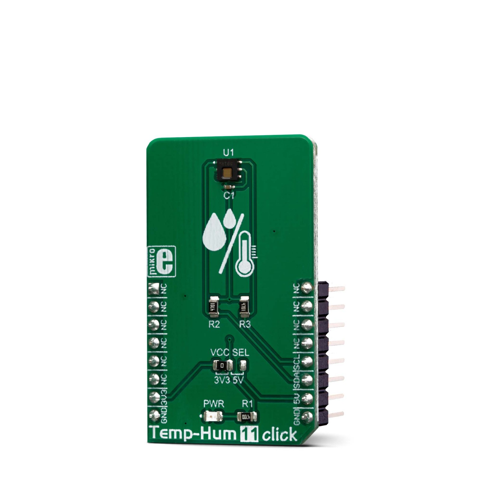
Temp-hum 11 click is a temperature and humidity sensing Click board™, equipped with the HDC1080, a high accuracy digital humidity, and temperature sensor. Its key features are its low power consumption, and the measurement accuracy achieved with that much energy. The HDC1080 sensor can sense the relative humidity (RH) with the accuracy of ±2%, while the temperature can be sensed with the accuracy up to ±0.2⁰C. It has a 14-bit measurement resolution, and it can be operated over a wide supply voltage range, allowing it to be interfaced with both 5V and 3.3V MCUs with no additional components required.
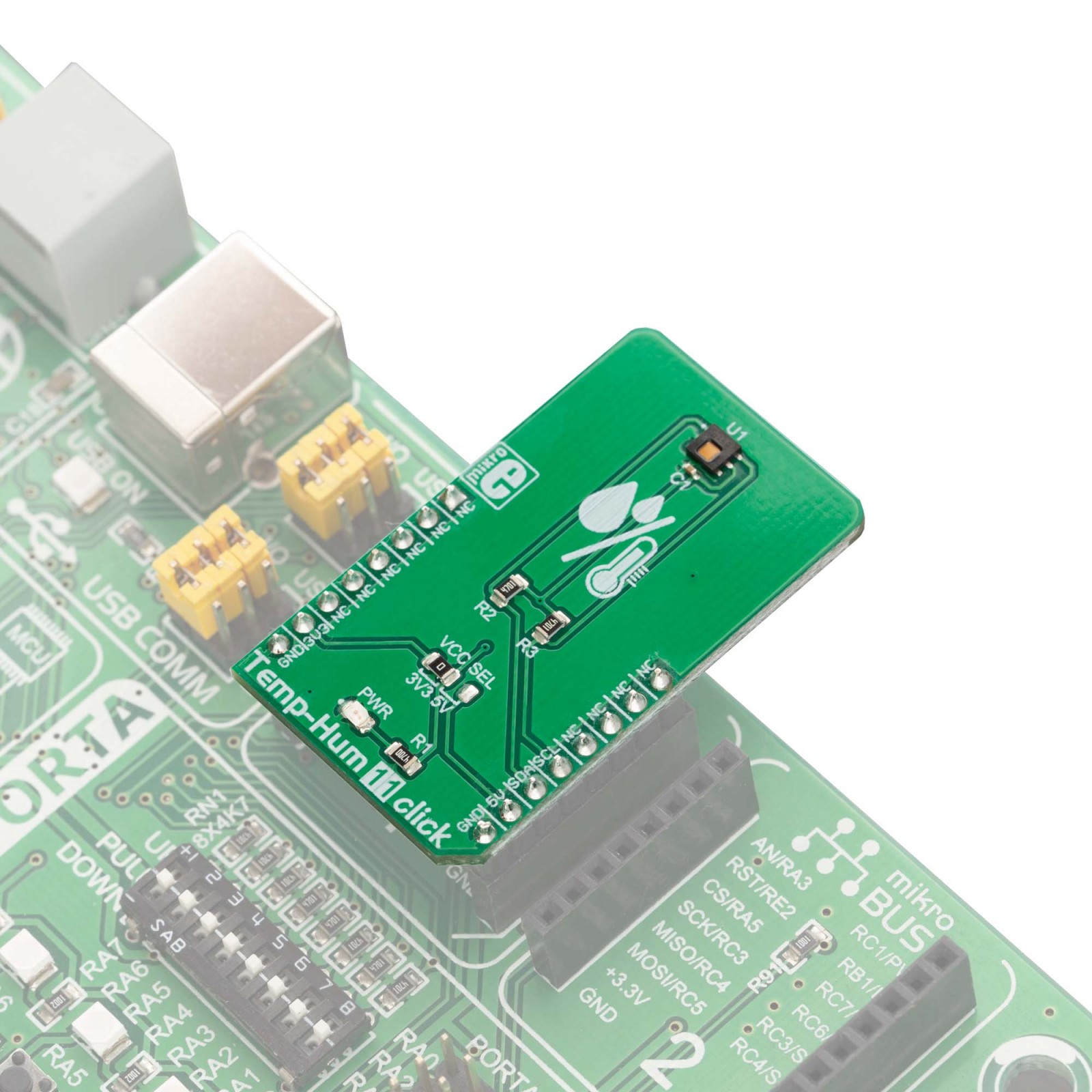
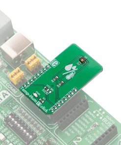
Temp-hum 11 click is supported by a mikroSDK compliant library, which includes functions that simplify software development. This Click board™ comes as a fully tested product, ready to be used on a system equipped with the mikroBUS™ socket.
Stock: Lead-time applicable.
| 5+ | R270.75 |
| 10+ | R256.50 |
| 15+ | R242.25 |
| 20+ | R233.13 |
Built with the power consumption in mind, the HDC1080 is an ideal solution for IoT development. A common problem for all humidity sensors is the memory effect or a hysteresis after prolonged exposure to extreme RH values for prolonged periods of time. Therefore, the HDC1080 is equipped with the heating element, reducing this offset and preventing condensation to be formed on the surface of the sensor. Low power consumption and high accuracy make the HDC1080 a perfect solution for various IoT RH and temperature measuring applications, smart homes, HVAC systems, air conditioner remote controllers, etc.
How does it work?
The sensor IC used on the Temp-Hum 11 click is the HDC1080, a low power humidity and temperature digital sensor from Texas Instruments. This sensor is factory calibrated to ±2% relative humidity and ±0.2°C temperature accuracy. It has an integrated heating element that is used to evaporate condensation, protecting the sensor that way. This heating element can be simply activated by setting a bit in the appropriate register. In the case when the heater is powered on, the typical current consumption is about 90mA.
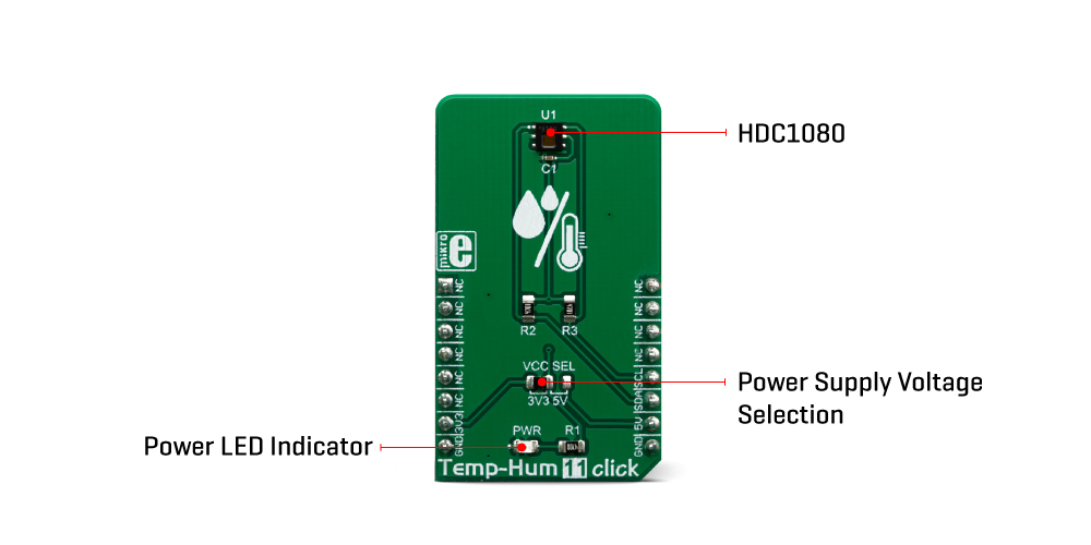
Internally, two sensors are connected to the 14-bit ADC section, which can be set to sample measurements with the resolution of 8, 11 or 14 bits, based on the measurement (integration) time. The OTP memory holds the calibration coefficients that are applied to the measured value and the results are stored on the output registers, in the MSB/LSB format. These values are then used in formulas found in the HDC1080 datasheet so that the final temperature or relative humidity data can be calculated.
HDC1080 IC is a very low power consuming device and it can work in two modes: sleep and active (measurement) mode. The device enters the sleep the mode as soon as possible, in order to save power. This makes the HDC1080 suitable to be used for battery-powered applications. In these applications, the HDC1080 can spend most of the time in the sleep mode that has a typical current consumption in the magnitude of nanoamperes. The measurement is triggered after the command is sent over the I2C interface. As soon as the single measurement is finished, the device falls back to a sleep mode. The host should wait for the acquisition to be completed before reading the output registers. However, the Click board™ is supported by a library of mikroSDK compatible functions, which simplify the development.
The heating element can be used to reduce the offset which is a common problem for most RH sensors. It also helps with the condensation, evaporating the excess moisture. The current consumption is increased when the heater is on. It can be enabled by configuring the appropriate register, but it won’t be actually activated until a measurement is triggered. Therefore, to increase its temperature, measurement frequency should be increased.
The Click board™ can be interfaced with both 3.3V and 5V MCUs without the need for any external components. Thanks to the HDC1080 and its support for a wide supply voltage range, the Click board™ can be simply used with any MCU that supports I2C communication.
Specifications
Type
Temperature & humidity
Applications
A perfect solution for various IoT based RH and temperature measuring applications, smart homes, HVAC systems, air conditioner remote controllers, etc.
On-board modules
HDC1080, a relative humidity and temperature sensor with I²C Interface, by Texas Instruments.
Key Features
High accuracy, good linearity, proven reliability, long-term stability, excellent repeatability, low power consumption, etc.
Interface
I2C
Feature
No ClickID
Compatibility
mikroBUS™
Click board size
M (42.9 x 25.4 mm)
Input Voltage
3.3V or 5V
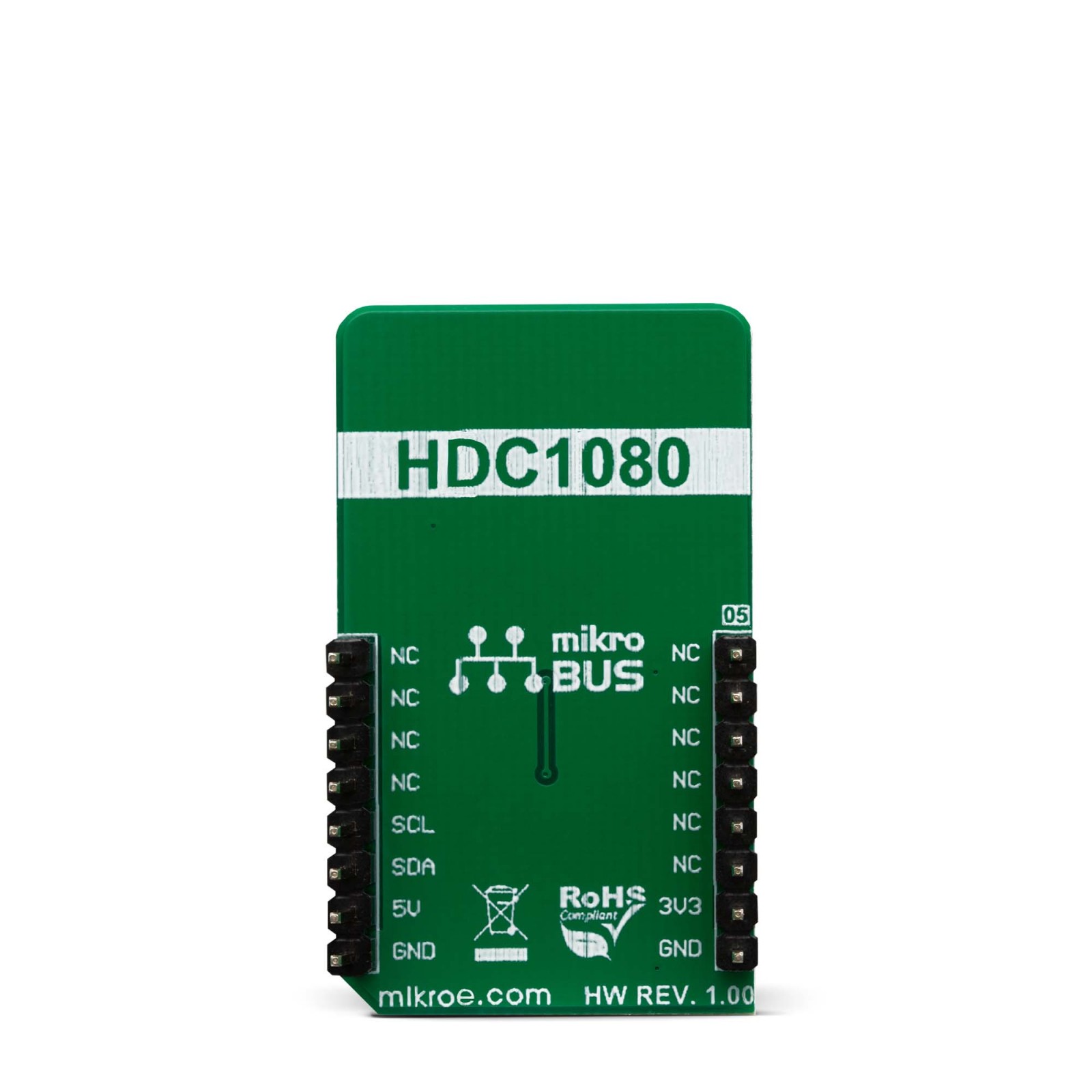
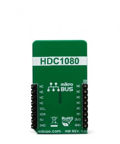
Pinout diagram
This table shows how the pinout on Temp&Hum 11 click corresponds to the pinout on the mikroBUS™ socket (the latter shown in the two middle columns).
Temp&Hum 11 click electrical specifications
| Description | Min | Typ | Max | Unit |
|---|---|---|---|---|
| Temperature Accuracy (5⁰C – 60⁰C) | – | +/-0.2 | +/-0.4 | °C |
| Humidity Accuracy | – | +/-2 | +/-3 | %RH |
| Operating temperature | -20 | – | 85 | °C |
| Relative Humidity Operating Range | 0 | – | 100 | %RH |
| I2C clock frequency | 10 | – | 400 | kHz |
Onboard settings and indicators
| Label | Name | Default | Description |
|---|---|---|---|
| PWR | PWR | – | Power LED indicator |
| JP1 | VCC SEL | Left | Power supply voltage selection: left position 3.3V, right position 5V |
Software support
We provide a library for the Temp&Hum 11 click on our LibStock page, as well as a demo application (example), developed using MikroElektronika compilers. The demo can run on all the main MikroElektronika development boards.
Library Description
The library initializes and defines the I2C bus driver and drivers that offer a choice for reads data form register. The library includes function for read Temperature and Relative Huminidy data and function for read device ID, Manifactures ID and Serial ID data. The user also has the function for configuration chip for measurement.
Key functions:
void temphum11_configuration(uint16_t config)– Functions for configuration device for measurement.float temphum11_getTemperature(uint8_t tempIn)– Functions for read Temperature data.float temphum11_getHumidity()– Functions for read Relative Huminidy data.
Examples description
The application is composed of the three sections :
- System Initialization – Initialization I2C module.
- Application Initialization – Initializes driver init, test comunication and configuration chip for measurement.
- Application Task – Reads Temperature and Humidity data. This data logs to USBUART every 1500ms.
void applicationTask()
{
    float Temperature;
    float Humidity;
    char demoText[ 50 ];

    Temperature = temphum11_getTemperature(_TEMPHUM11_TEMP_IN_CELSIUS);

    FloatToStr(Temperature, demoText);
    mikrobus_logWrite(" Temperature : ", _LOG_TEXT);
    mikrobus_logWrite(demoText, _LOG_LINE);

    Humidity = temphum11_getHumidity();

    FloatToStr(Humidity, demoText);
    mikrobus_logWrite(" Humidity : ", _LOG_TEXT);
    mikrobus_logWrite(demoText, _LOG_LINE);

    mikrobus_logWrite("-----------------", _LOG_LINE);
    Delay_ms( 1500 );
}
The full application code, and ready to use projects can be found on our LibStock page.
Other mikroE Libraries used in the example:
I2CUARTConversions
Additional notes and informations
Depending on the development board you are using, you may need USB UART click, USB UART 2 click or RS232 click to connect to your PC, for development systems with no UART to USB interface available on the board. The terminal available in all MikroElektronika compilers, or any other terminal application of your choice, can be used to read the message.
mikroSDK
This click board is supported with mikroSDK - MikroElektronika Software Development Kit. To ensure proper operation of mikroSDK compliant click board demo applications, mikroSDK should be downloaded from the LibStock and installed for the compiler you are using.
For more information about mikroSDK, visit the official page.
Resources
Downloads
| Weight | 18 g |
|---|---|
| Brand | MikroElektronika |

