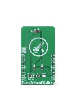
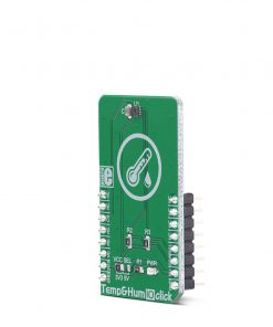
Temp&Hum 10 Click
R340.00 ex. VAT
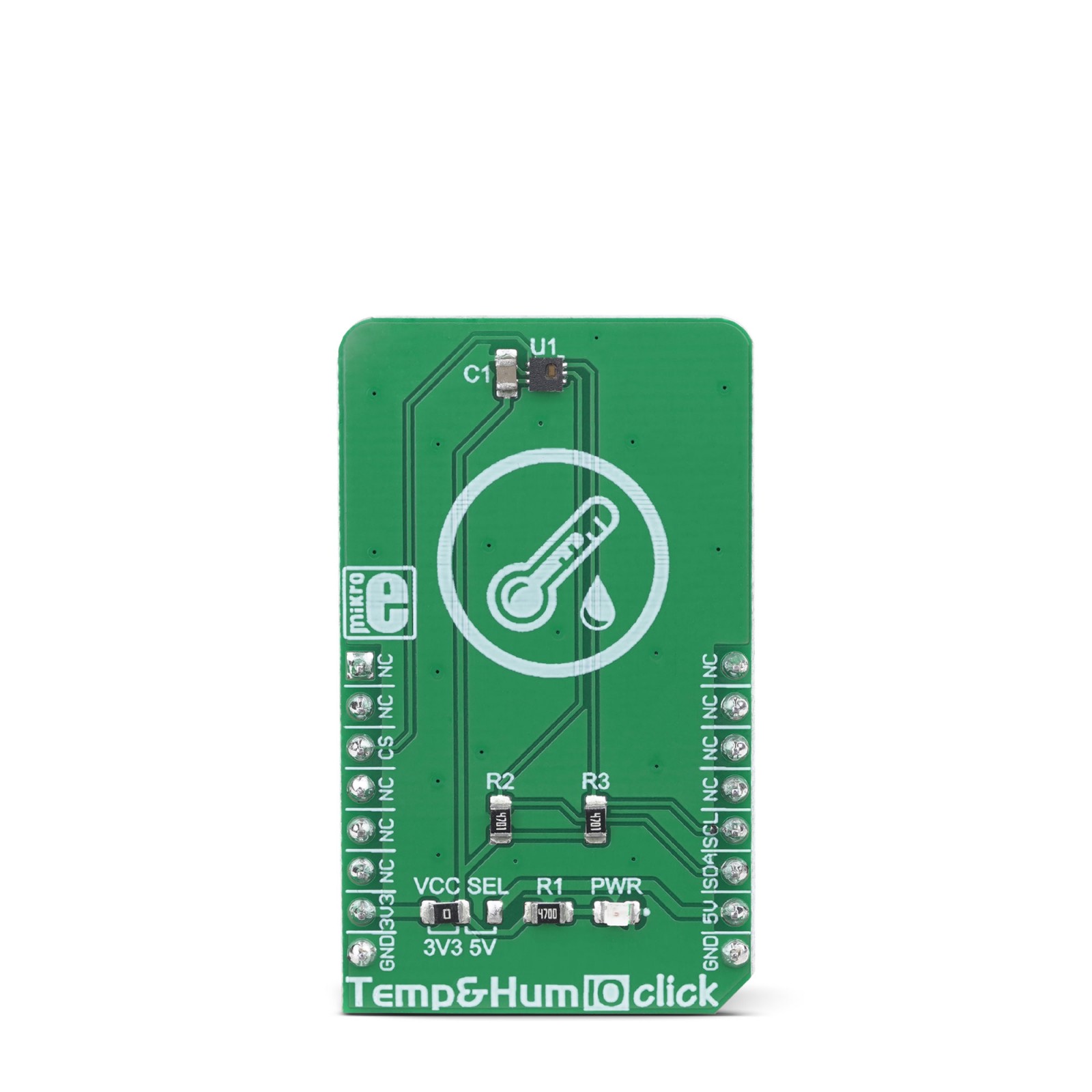
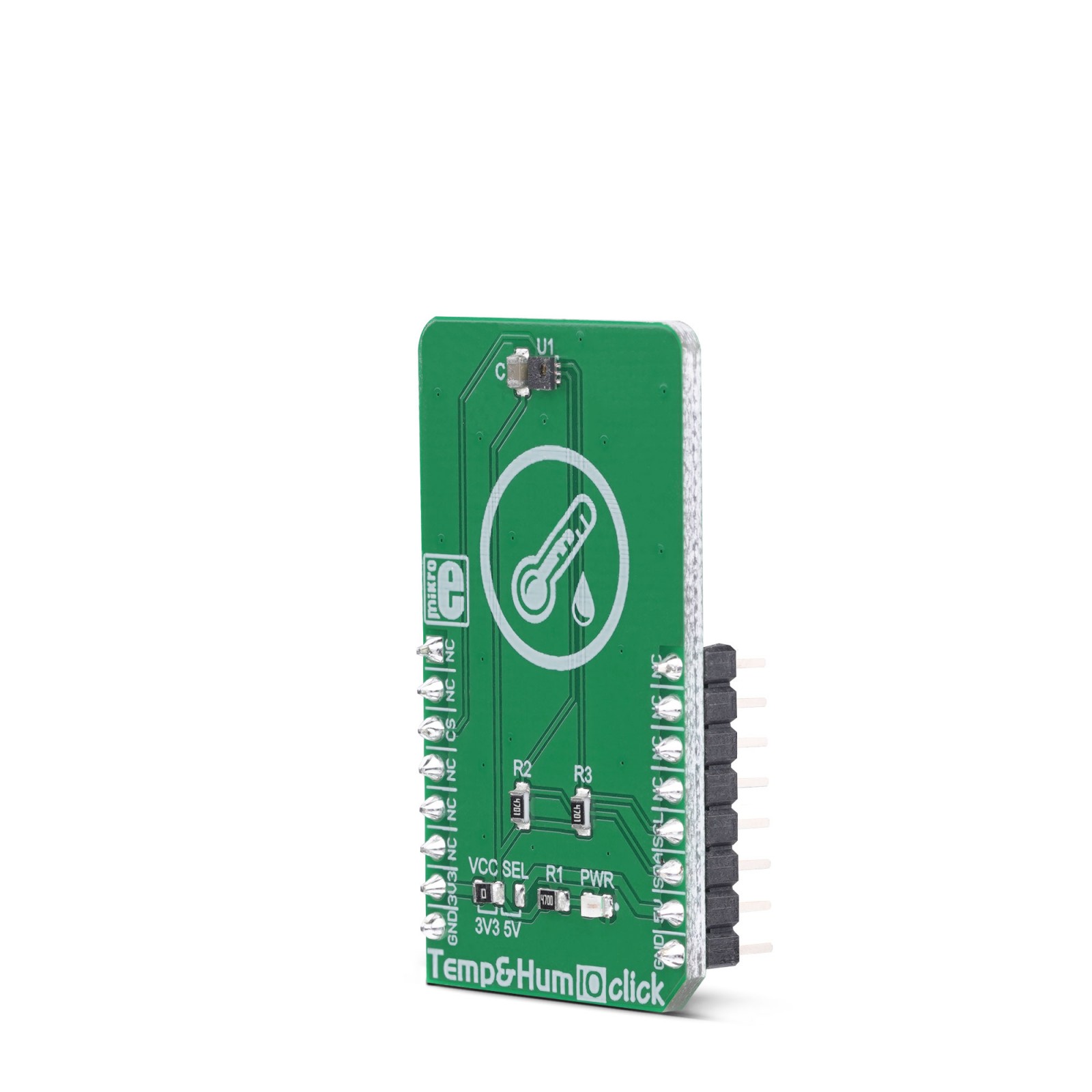
Temp&Hum 10 Click is a smart temperature and humidity sensing Click board™, aimed towards IoT applications, due to its extremely small size and very low power consumption. It can measure a wide range of temperature and relative humidity (RH) values with high accuracy. The sensor used on this Click board™ offers the complete measurement system: capacitive RH sensor, thermal sensor, analog and digital data processing, and the I2C communication interface. Featuring a good reliability over time, high accuracy, and low hysteresis, it is an ideal solution to be used in various temperature and humidity related IoT applications.
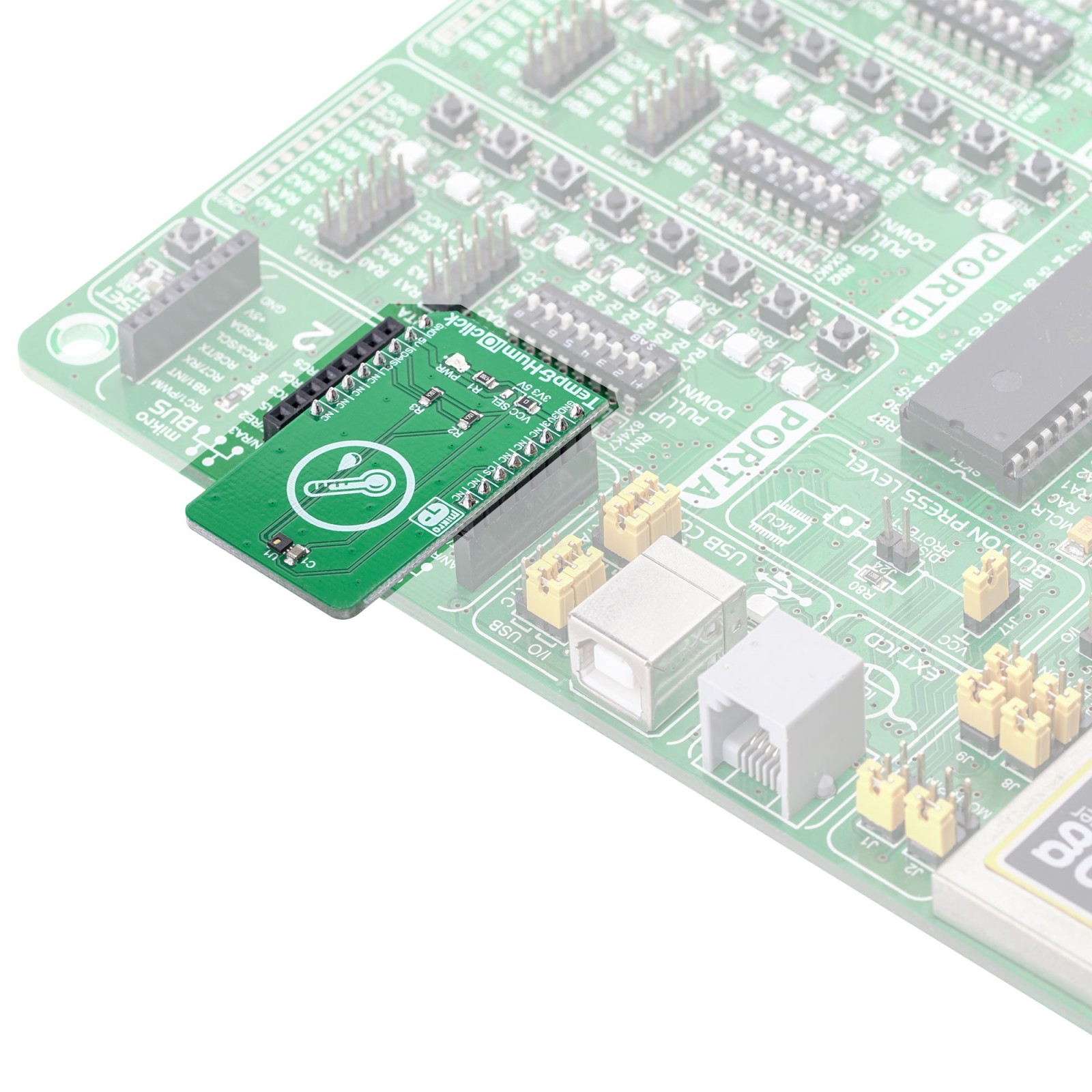
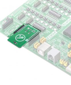
Temp&Hum 10 click is supported by a mikroSDK compliant library, which includes functions that simplify software development. This Click board™ comes as a fully tested product, ready to be used on a system equipped with the mikroBUS™ socket.
Stock: Lead-time applicable.
| 5+ | R323.00 |
| 10+ | R306.00 |
| 15+ | R289.00 |
| 20+ | R278.12 |
Temp&Hum 10 click can measure the humidity in the range from 0 to 100 %RH and temperature in the range from -30 °C to +100 °C, with the typical accuracy of ±3 %RH and ±0.4 ℃. It consumes small amounts of power while in operation, delivering processed and calibrated measurement values over the I2C interface. Thanks to its high reliability and long-term stability, Temp&Hum 10 click is perfectly suited for battery operated weather stations, thermostats and humidistats, microenvironment centers, respiratory therapy applications, air conditioners, and other similar applications. Due to its low power consumption, this Click board™ is a good solution for development of IoT-based and battery powered applications.
How does it work?
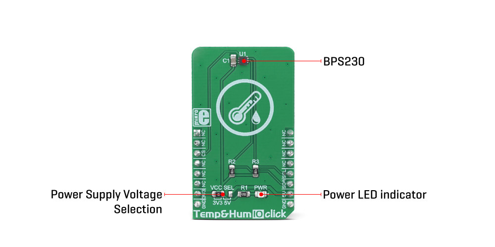
The main component of Temp&Hum 10 click is the BPS230, a relative humidity and temperature sensor with I²C Interface, by Bourns. This sensor IC integrates two very accurate sensing components: temperature sensor, and relative humidity sensor. By utilizing the proprietary manufacturing technology, this sensor integrates the complete temperature and humidity measurement system on chip. The output data is processed and compensated by the BPS230 sensor IC itself, requiring only basic conversion formulas to be applied within the firmware of the host microcontroller (MCU). These conversion formulas are given in the BPS230 datasheet and provide readings in °C and %RH, directly.
The BPS230 incorporates an accurate bandgap temperature sensor, which can measure the temperature in the range between -30 °C and 100 °C while retaining accuracy of ±0.4°C, typically. The accuracy is even greater if the range is narrowed down: when used over the range between -10°C and 70°C, the typical accuracy is ±0.1 °C. Also, the reproducibility of the temperature measurement is very good, in the range of 0.1°C. The BPS230 sensor IC can be reliably used for prolonged periods of time.
After the measurement has been converted by a high-precision ADC, it is fed to a logic back-end which applies factory-calibrated correction and converts the raw data into a compensated value. By applying a simple conversion formula, the measurement can be easily converted in °C. The raw temperature measurement value is in the 11-bit format. Please note that the sensor will take some time to accommodate to the ambient temperature, especially if the temperature changes quickly, considering the thermal conductivity of the PCB itself. The response time of both sensors is also affected by the averaging ratio, which can be configured over the I2C interface.
The humidity sensor is a capacitor type polymer-based sensor which changes the capacitance proportionally to the relative humidity. However, the capacitance of this sensor is affected by changes of the ambient temperature, as well. The accuracy of the RH sensor varies in the range between ±3% and ±5%, depending on the measurement conditions (ambient temperature).
After the measurement has been converted by a high-precision ADC, it is fed to the logic back-end which applies factory-calibrated correction and converts the raw data into a compensated value. By applying a simple conversion formula, the measurement can be easily converted in %RH. The raw RH measurement value is in the 10-bit format. Please note that capacitor-based humidity sensors commonly suffer from a small hysteresis, which may occur if the sensor is used in very humid conditions for prolonged periods of time. However, this hysteresis is not irreversible. The BPS230 datasheet specifies that its hysteresis should stay within the range of ±1 %RH.
The CS pin of the mikroBUS™ is routed to the CE pin of the BPS230 sensor IC. This pin is used to set the operating mode of the sensor by the host MCU either in Sleep or StandBy mode. When there is a LOW logic level on the CS pin, the device operates in Sleep mode. While in Sleep mode, the power consumption is reduced to a minimum: the internal clock of the IC is stopped, and the I2C interface is disabled. By applying a HIGH logic level to this pin, the IC enters the StandBy mode, with the I2C interface enabled.
Temp&Hum 10 click uses the I2C communication interface. It has pull-up resistors connected to a selectable voltage source. A small SMD jumper can be used to switch between 3.3V and 5V. This jumper switches the voltage for both the IC and two pull-up resistors, allowing the Click board™ to be used with a wide range of MCUs, both using 3.3V and 5V.
Specifications
Type
Temperature & humidity
Applications
This Click board™ is an ideal solution for development of a range of different applications, including battery operated weather stations, thermostats and humidistats, microenvironment centers, respiratory therapy applications, air conditioners, etc.
On-board modules
BPS230, a relative humidity and temperature sensor with I²C Interface, by Bourns.
Key Features
Integrated data calibration and processing, high accuracy, low drift over time, high repeatability, low power consumption…
Interface
I2C
Feature
No ClickID
Compatibility
mikroBUS™
Click board size
M (42.9 x 25.4 mm)
Input Voltage
3.3V or 5V
Pinout diagram
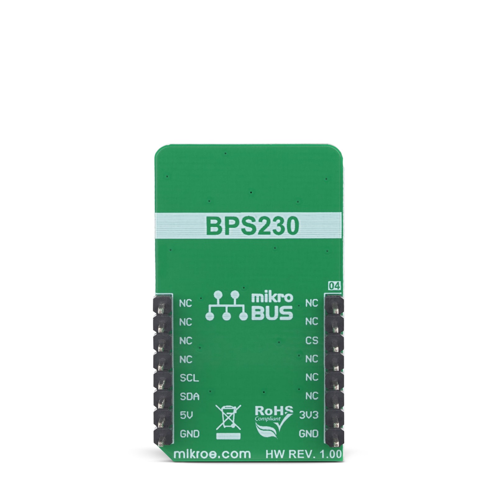
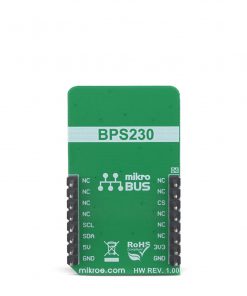
This table shows how the pinout on Temp&Hum 10 Click corresponds to the pinout on the mikroBUS™ socket (the latter shown in the two middle columns).
Onboard settings and indicators
| Label | Name | Default | Description |
|---|---|---|---|
| PWR | PWR | – | Power LED indicator |
| JP1 | VCC SEL | Left | Power supply voltage selection: left position 3.3V, right position 5V |
Software support
We provide a library for the Temp&Hum 10 Click on our LibStock page, as well as a demo application (example), developed using MikroElektronika compilers. The demo can run on all the main MikroElektronika development boards.
Library Description
The library initializes and defines the I2C bus driver and drivers that offer a choice for writing data in register and reads data form register. The library includes function for read Temperature and Relative Huminidy data and function for set device mode. The user also has the function for repeat measurement.
Key functions:
float temphum10_getHumidity()– Functions for read Relative Huminidy data.float temphum10_getTemperature()– Functions for read Temperature datavoid temphum10_repeatMeasurement(uint8_t average)– Functions for repeat measurement.
Examples description
The application is composed of the three sections :
- System Initialization – Initializes I2C module and sets CS pin as OUTPUT.
- Application Initialization – Initialization driver init and sets device mode.
- Application Task – (code snippet) – Reads Temperature and Humidity data and logs this data to USBUART every 1 sec.
void applicationTask()
{
    temphum10_repeatMeasurement(_TEMPHUM10_AM_TIMES_AVERAGE_MODE_2 | _TEMPHUM10_AM_TEMP_AVERAGE_MODE_TIMES_16);

    Temperature = temphum10_getTemperature();
    Humidity = temphum10_getHumidity();

    FloatToStr(Temperature, demoText);
    mikrobus_logWrite(" Temperature : ", _LOG_TEXT);
    mikrobus_logWrite(demoText, _LOG_LINE);

    FloatToStr(Humidity, demoText);
    mikrobus_logWrite(" Humidity : ", _LOG_TEXT);
    mikrobus_logWrite(demoText, _LOG_LINE);

    mikrobus_logWrite("---------------------", _LOG_LINE);

    Delay_1sec();
}
The full application code, and ready to use projects can be found on our LibStock page.
Other mikroE Libraries used in the example:
I2CUARTConversions
Additional notes and informations
Depending on the development board you are using, you may need USB UART click, USB UART 2 click or RS232 click to connect to your PC, for development systems with no UART to USB interface available on the board. The terminal available in all MikroElektronika compilers, or any other terminal application of your choice, can be used to read the message.
mikroSDK
This click board is supported with mikroSDK - MikroElektronika Software Development Kit. To ensure proper operation of mikroSDK compliant click board demo applications, mikroSDK should be downloaded from the LibStock and installed for the compiler you are using.
For more information about mikroSDK, visit the official page.
Resources
Downloads
| Weight | 18 g |
|---|---|
| Brand | MikroElektronika |

