Temp Probe Click
R2,250.00 ex. VAT
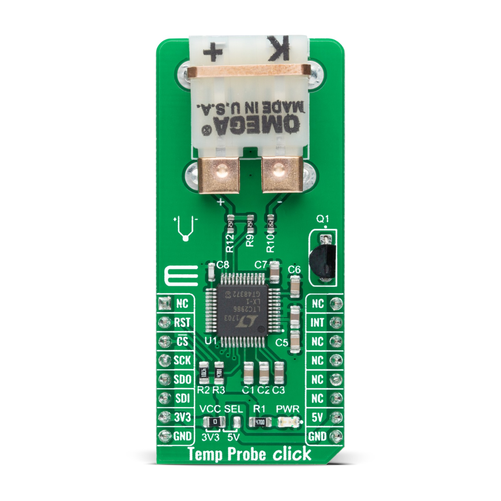
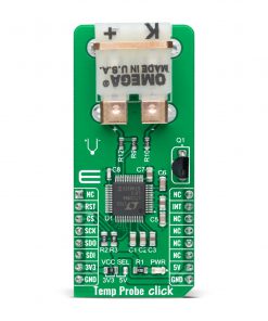
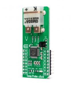
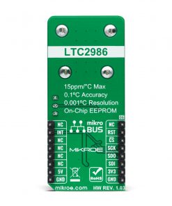
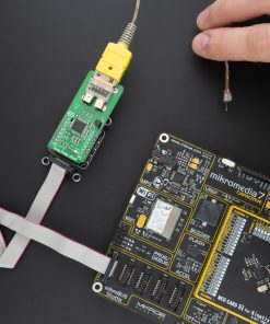
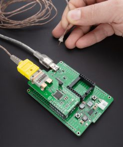
Temp Probe Click is a compact add-on board used as thermocouple temperature monitoring system. This board features the LTC2986, a high accuracy digital temperature measurement system used to directly digitize thermocouples with 0.1°C accuracy and 0.001°C resolution from Analog Devices. The LTC2986 includes all necessary active circuitry, switches, measurement algorithms, and mathematical conversions to determine the thermocouple temperature with a PCC-SMP connector for K-type thermocouple probes. Also, it includes excitation current sources, fault detection circuitry, and automatic thermocouple cold junction compensation. This Click board™ is suitable for temperature-monitoring applications such as direct thermocouple measurements.
Temp Probe Click is supported by a mikroSDK compliant library, which includes functions that simplify software development. This Click board™ comes as a fully tested product, ready to be used on a system equipped with the mikroBUS™ socket.
Stock: Lead-time applicable.
| 5+ | R2,137.50 |
| 10+ | R2,025.00 |
| 15+ | R1,912.50 |
| 20+ | R1,840.50 |
NOTE: Thermocouple Type-K Glass Braid does not come with this Click board™, if you are interested you can find Thermocouple Type-K Glass Braid Insulated in our shop.
How does it work?
Temp Probe Click is based on the LTC2986, a high accuracy thermocouple temperature monitoring system with 0.1°C accuracy and 0.001°C resolution from Analog Devices. The LTC2986 simultaneously measures the thermocouple output and the cold junction temperature and performs all required calculations to report the thermocouple temperature in °C or °F. It combines high accuracy with the simple operation composed of five states: Start-Up, Channel Assignment, Initiate Conversion, Conversion, and Read Results. It works with ground-referenced sensors without the need for amplifiers, negative supplies, or level shift circuitry where signals are simultaneously digitized with three, high accuracy, 24-bit Δ-Σ ADCs using an internal 15ppm/°C reference.
.jpg)
Thermocouples can measure temperatures from –265°C to more than 1.800°C, generating a voltage as a function of the temperature difference between the tip (thermocouple temperature) and the electrical connection on the circuit board (cold junction temperature). In order to determine the thermocouple temperature, an accurate measurement of the cold junction temperature is required, known as cold junction compensation. The LTC2986 preforms automatic thermocouple cold junction compensation using any type of external sensor.
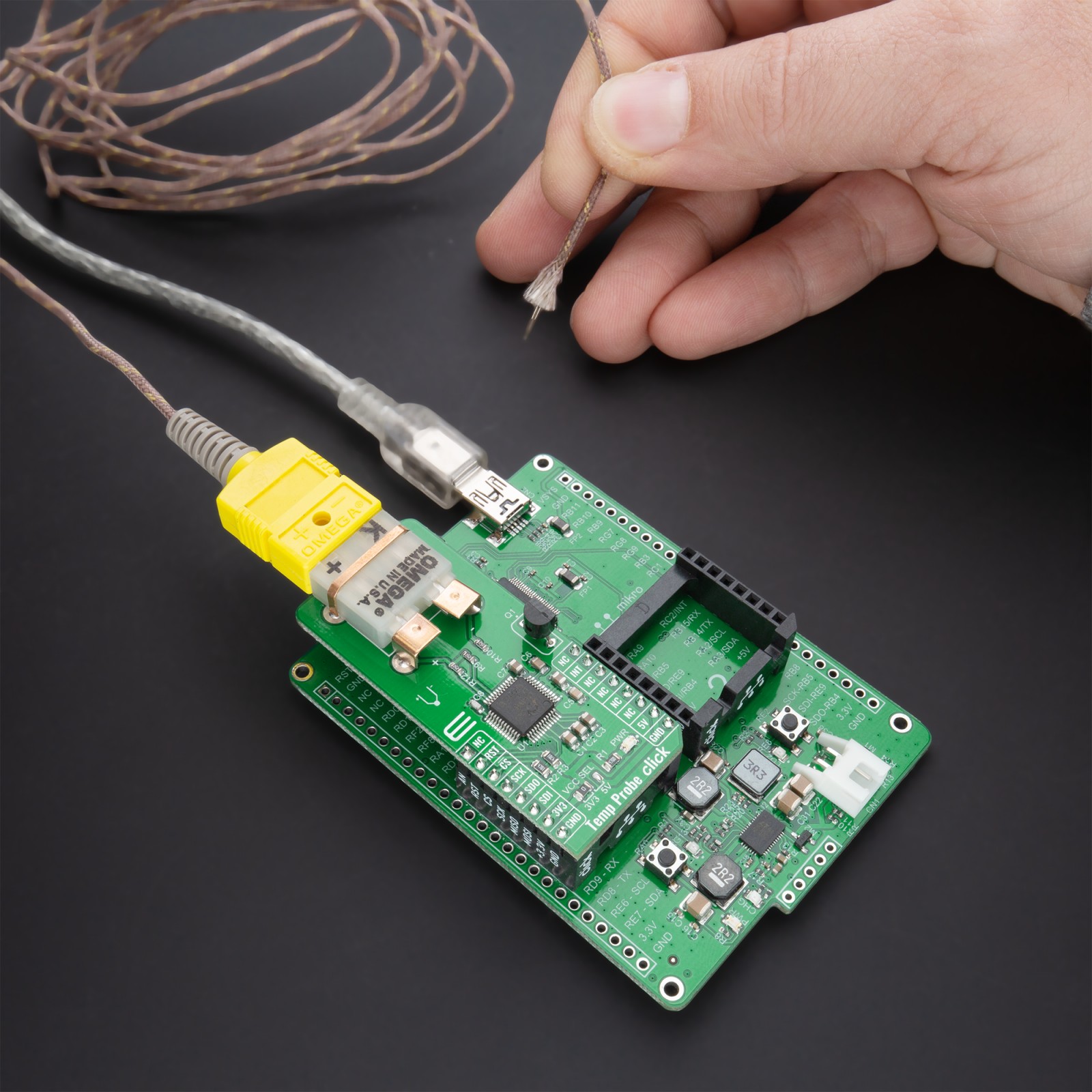
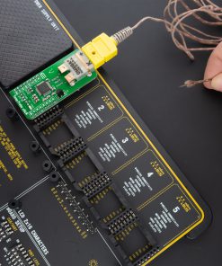
The onboard PCC-SMP connector is a perfect solution for bringing thermocouple probes to the PCB, suitable for all K-type probes. To use Temp Probe Click user needs to connect the appropriate K-type thermocouple probe, which is not included in the package, into the PCC-SMP connector. Type-K thermocouple with glass braid insulation, available in our store, is used for precision measurements of high temperatures allowing this Click board™ to measure temperature up to 480°C (900°F).
Temp Probe Click communicates with MCU using the SPI serial interface with a maximum SPI frequency of 2 MHz. The interrupt pin routed on the INT pin of the mikroBUS™ socket is utilized by LTC2986 to signal when the device is busy either during Start-Up or while a conversion cycle is in progress. Alongside this feature, this Click board™ also has a Reset function routed on the RST pin of the mikroBUS™ socket that will put the LTC2986 into the reset state by driving the RST pin LOW. Once this pin is returned HIGH, the device initiates its Start-Up sequence.
This Click board™ is designed to operate with both 3.3V and 5V logic voltage levels selected via the VCC SEL jumper. It allows for both 3.3V and 5V capable MCUs to use the SPI communication lines properly. However, the Click board™ comes equipped with a library that contains easy to use functions and an example code which can be used, as a reference, for further development.
Specifications
Type
Temperature & humidity
Applications
Can be used for temperature-monitoring applications such as direct thermocouple measurements.
On-board modules
Temp Probe Click is based on the LTC2986, a high accuracy thermocouple temperature monitoring system with 0.1°C accuracy and 0.001°C resolution from Analog Devices.
Key Features
High accuracy, directly digitizes, automatic thermocouple cold junction compensation, short-circuit and fault detection, and more.
Interface
SPI
Feature
No ClickID
Compatibility
mikroBUS™
Click board size
L (57.15 x 25.4 mm)
Input Voltage
3.3V or 5V
Pinout diagram
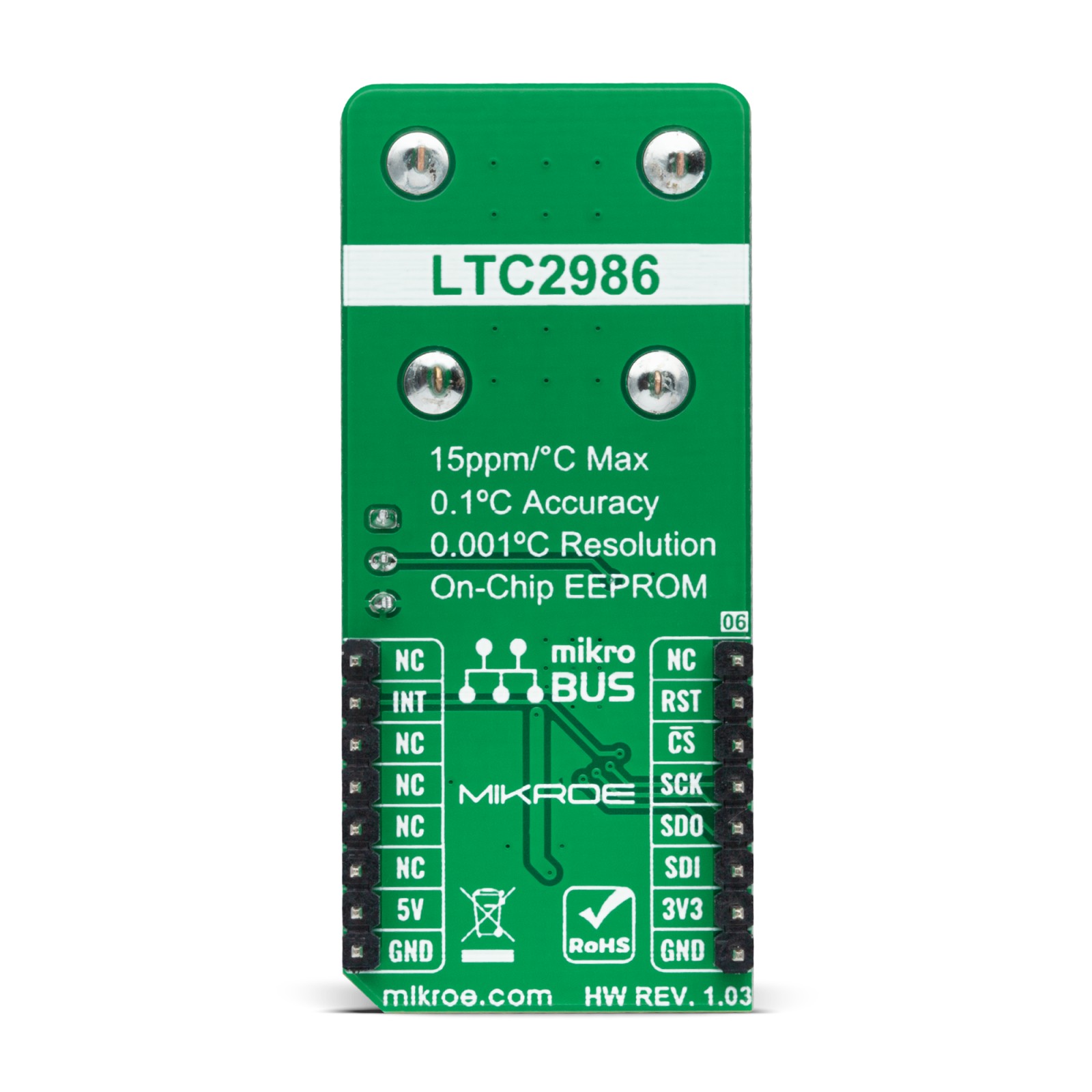
This table shows how the pinout on Temp Probe Click corresponds to the pinout on the mikroBUS™ socket (the latter shown in the two middle columns).
Onboard settings and indicators
| Label | Name | Default | Description |
|---|---|---|---|
| LD1 | PWR | – | Power LED Indicator |
| JP1 | VCC SEL | Left | Power Supply Voltage Selection 3V3/5V: Left position 3V3, Right position 5V |
Temp Probe Click electrical specifications
| Description | Min | Typ | Max | Unit |
|---|---|---|---|---|
| Supply Voltage | -0.3 | – | 6 | V |
| K-Type Thermocouple Measurement Range | – | – | 480 | °C |
| Resolution | 24 | – | – | bits |
| Accuracy | – | +/- 0.1 | – | °C |
| Operating Temperature Range | 0 | – | +70 | °C |
Software Support
We provide a library for the Temp Probe Click on our LibStock page, as well as a demo application (example), developed using MikroElektronika compilers. The demo can run on all the main MikroElektronika development boards.
Library Description
Library performs a control of the Temp Probe Click board™ and performs a configuration on which way temperature be measured. Library offers a choice to measure temperature on the desired channel/channels, depending on the cold junction channel. The device can use a lot of different sensors for measurement, such as thermocouples, diodes, sense resistors, thermistors… For more details check documentation.
Key functions:
uint8_t tempprobe_write_byte( uint16_t reg_addr, uint8_t data_in )– .uint8_t tempprobe_read_word( uint16_t reg_addr, uint32_t *data_out )– .uint8_t tempprobe_write_eeprom( void )– Function writes the current settings from the chip registers to the EEPROM memory and checks is error occurred.uint8_t tempprobe_read_temp( uint16_t sel_channel, float *data_out )– Function reads temperature data from the desired channel.
Examples description
The application is composed of three sections :
- System Initialization – Initializes peripherals and pins.
- Application Initialization – Initializes SPI interface and performs a device configuration for properly working. Configures the desired channels and offers a choice to choose in which format temperature be measured. Temperature format can be celsius or fahrenheit.
- Application Task – Allows start of the conversion for the selected (masked) channels and when conversion cycle is done, reads temperature from channel 10, on which the thermocouple type K sensor is connected. The cold junction channel is channel 9, on which sensor measures the ambient temperature.
void application_task ( )
{
    uint8_t check_state;

    tempprobe_write_byte( TEMPPROBE_REG_COMM_STATUS, TEMPPROBE_START_CONV  );
    check_state = tempprobe_check_busy( );

    while ( check_state != TEMPPROBE_NO_BUSY_STATE )
    {
        check_state = tempprobe_check_busy( );
    }

    mikrobus_logWrite( ">> PN-Junction: ", _LOG_TEXT );
    tempprobe_read_temp( TEMPPROBE_REG_PN_JUNCTION_CONV_RES , &temperature_k );
    FloatToStr( temperature_k, demo_text );
    mikrobus_logWrite( demo_text, _LOG_LINE );

    mikrobus_logWrite(">> Thermo K: ", _LOG_TEXT );
    tempprobe_read_temp( TEMPPROBE_REG_THERMO_K_CONV_RES, &temperature_pn );
    FloatToStr( temperature_pn, demo_text );
    mikrobus_logWrite( demo_text, _LOG_LINE );

    Delay_ms( 1500 );
}
The full application code, and ready to use projects can be found on our LibStock page.
Other mikroE Libraries used in the example:
- Conversions
- SPI
- UART
Additional notes and informations
Depending on the development board you are using, you may need USB UART click, USB UART 2 click or RS232 click to connect to your PC, for development systems with no UART to USB interface available on the board. The terminal available in all MikroElektronika compilers, or any other terminal application of your choice, can be used to read the message.
mikroSDK
This Click board™ is supported with mikroSDK – MikroElektronika Software Development Kit. To ensure proper operation of mikroSDK compliant Click board™ demo applications, mikroSDK should be downloaded from the LibStock and installed for the compiler you are using.
For more information about mikroSDK, visit the official page.
Resources
Downloads
| Weight | 23 g |
|---|---|
| Brand | MikroElektronika |

