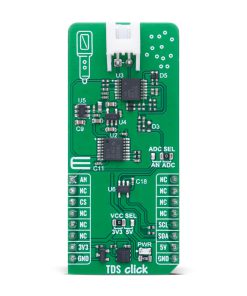
TDS Click
R455.00 ex. VAT
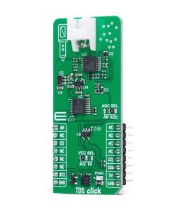
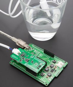
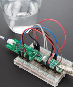
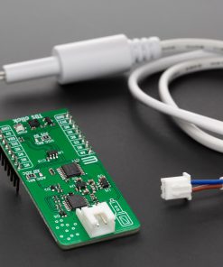
TDS Click is a compact add-on board used to measure Total Dissolved Solids (TDS) in water, providing an accurate indicator of water quality. This board features the CD4060B oscillator from Texas Instruments, supported by the LMV324 op-amp, MCP3221 ADC from Microchip, and dual-voltage regulation using LP2985AIM5-3.0 and ADM8829. It features a multi-stage signal conditioning circuit that amplifies, rectifies, and filters the signal from the connected TDS probe, delivering a clean DC voltage proportional to the TDS level. The output can be accessed either as an analog voltage or a digital I2C signal, selectable via the onboard ADC SEL jumper. Operating with both 3.3V and 5V logic levels, it ensures broad MCU compatibility. TDS Click is ideal for applications in water quality monitoring, filtration systems, hydroponics, and environmental sensing.
TDS Click is fully compatible with the mikroBUS™ socket and can be used on any host system supporting the mikroBUS™ standard. It comes with the mikroSDK open-source libraries, offering unparalleled flexibility for evaluation and customization. What sets this Click board™ apart is the groundbreaking ClickID feature, enabling your host system to seamlessly and automatically detect and identify this add-on board.
Stock: Lead-time applicable.
| 5+ | R432.25 |
| 10+ | R409.50 |
| 15+ | R386.75 |
| 20+ | R372.19 |
How does it work?
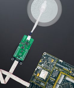
TDS Click is designed to measure the Total Dissolved Solids (TDS) levels in water, providing a reliable indication of water quality. The measurement process begins with the connection of an external TDS Water Quality Testing Probe via the onboard connector positioned at the top of the board. This probe detects the amount of dissolved solids in water, a crucial parameter for assessing overall water purity. At the heart of the circuit is the CD4060B from Texas Instruments, a key component responsible for generating the clock signal required to drive the TDS probe. This oscillator circuit operates on a dual supply voltage of +3.0V and -3.0V, which is essential for the subsequent signal processing stages. The voltage regulation is handled by two additional components: U4 (LP2985AIM5-3.0) delivers a stable +3.0V output from the selected mikroBUS™ power rail (VCC SEL), while U5 (ADM8829) performs voltage inversion, generating -3.0V from the generated 3.0V source. These voltages are necessary to power the operational amplifiers used in the signal conditioning chain.

The core signal conditioning and amplification tasks are performed by the LMV324, a rail-to-rail operational amplifier also from Texas Instruments. Initially, one stage of the op-amp is used to amplify the oscillator signal, providing enough drive for the connected TDS probe. The signal from the probe then passes through multiple additional stages of the LMV324, each serving a specific function in preparing the signal for final measurement. These stages buffer or further amplify the weak input from the probe, then rectify it to convert the AC signal into a positive DC waveform. This waveform is then filtered, resulting in a clean DC voltage that accurately represents the TDS concentration in the tested water.
This final processed signal is routed to the ADC SEL jumper, which gives the user flexibility to select between analog and digital output modes. If the analog output is preferred, the signal can be accessed directly through the AN pin of the mikroBUS™ socket. For digital conversion, the board integrates the MCP3221 from Microchip, a 12-bit resolution analog-to-digital converter that communicates over a standard 2-wire I2C interface. The mode selection is easily configured via the onboard SMD jumper labeled ADC SEL, allowing users to switch between the analog (AN) and digital (ADC) output positions according to their application needs.
This Click board™ can operate with either 3.3V or 5V logic voltage levels selected via the VCC SEL jumper. This way, both 3.3V and 5V capable MCUs can use the communication lines properly. Also, this Click board™ comes equipped with a library containing easy-to-use functions and an example code that can be used as a reference for further development.
Specifications
Type
Environmental,Measurements
Applications
Ideal for applications in water quality monitoring, filtration systems, hydroponics, and environmental sensing
On-board modules
CD4060B – binary counter with a built-in oscillator from Texas Instruments
Key Features
Total Dissolved Solids (TDS) measurement, oscillator-based signal generation, multi-stage analog signal conditioning, rail-to-rail operational amplifier, bipolar power supply generation, analog and digital output selection, 12-bit ADC with I2C interface, and more
Interface
Analog,I2C
Feature
ClickID
Compatibility
mikroBUS™
Click board size
L (57.15 x 25.4 mm)
Input Voltage
3.3V or 5V
Pinout diagram
This table shows how the pinout on TDS Click corresponds to the pinout on the mikroBUS™ socket (the latter shown in the two middle columns).
| Notes | Pin | Pin | Notes | ||||
|---|---|---|---|---|---|---|---|
| Analog Output | AN | 1 | AN | PWM | 16 | NC | |
| NC | 2 | RST | INT | 15 | NC | ||
| ID COMM | CS | 3 | CS | RX | 14 | NC | |
| NC | 4 | SCK | TX | 13 | NC | ||
| NC | 5 | MISO | SCL | 12 | SCL | I2C Clock | |
| NC | 6 | MOSI | SDA | 11 | SDA | I2C Data | |
| Power Supply | 3.3V | 7 | 3.3V | 5V | 10 | 5V | Power Supply |
| Ground | GND | 8 | GND | GND | 9 | GND | Ground |
Onboard settings and indicators
| Label | Name | Default | Description |
|---|---|---|---|
| LD1 | PWR | – | Power LED Indicator |
| JP1 | VCC SEL | Left | Power Voltage Level Selection 3V3/5V: Left position 3V3, Right position 5V |
| JP2 | ADCSEL | Right | Output Voltage A/D Selection AN/ADC: Left position AN, Right position ADC |
TDS Click electrical specifications
| Description | Min | Typ | Max | Unit |
|---|---|---|---|---|
| Supply Voltage | 3.3 | – | 5 | V |
Software Support
TDS Click demo application is developed using the NECTO Studio, ensuring compatibility with mikroSDK‘s open-source libraries and tools. Designed for plug-and-play implementation and testing, the demo is fully compatible with all development, starter, and mikromedia boards featuring a mikroBUS™ socket.
Example Description
This example demonstrates the usage of the TDS Click board, which measures the Total Dissolved Solids (TDS) in water. The application initializes the TDS Click board, establishes communication, and continuously reads the TDS value in parts per million (ppm).
Key Functions
tds_cfg_setupThis function initializes Click configuration structure to initial values.tds_initThis function initializes all necessary pins and peripherals used for this Click board.tds_set_vrefThis function sets the voltage reference for TDS Click driver.tds_read_voltage_avgThis function reads a desired number of ADC samples and calculates the average voltage level.tds_read_ppmThis function reads the TDS measurement value in ppm.
Application Init
Initializes the logger and configures the TDS Click board. It sets up communication using either ADC or I2C, verifies proper initialization, and prepares the device for measurement.
Application Task
Continuously reads the TDS value from the sensor and logs it in ppm (parts per million).
Application Output
This Click board can be interfaced and monitored in two ways:
- Application Output – Use the “Application Output” window in Debug mode for real-time data monitoring. Set it up properly by following this tutorial.
- UART Terminal – Monitor data via the UART Terminal using a USB to UART converter. For detailed instructions, check out this tutorial.
Additional Notes and Information
The complete application code and a ready-to-use project are available through the NECTO Studio Package Manager for direct installation in the NECTO Studio. The application code can also be found on the MIKROE GitHub account.
Resources
Downloads
| Weight | 19 g |
|---|---|
| Brand | MikroElektronika |