How does it work?
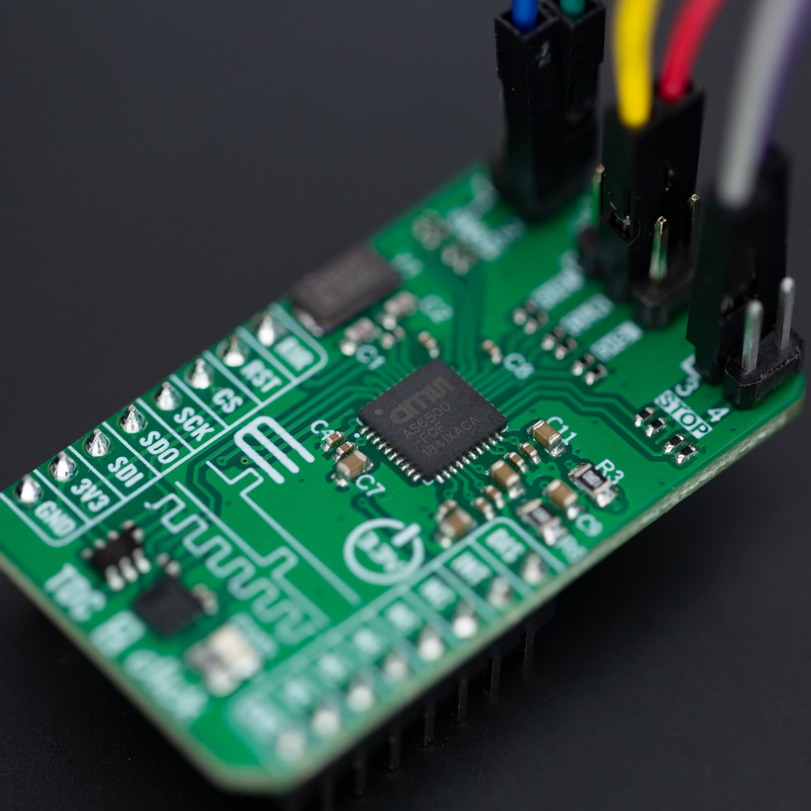
TDC 2 Click is based on the AS6500, a high-resolution time-to-digital converter from ScioSense, featuring CMOS inputs, high measurement performance, and high data throughput. The AS6500 can measure time intervals as low as 5ns with 10ps resolution on all four STOP channels at a sampling rate of up to 1.5Ms/s. It is characterized by high configuration flexibility, a wide measurement range from 0 to 16s, and simple data post-processing thanks to calibrated results. It calculates calibrated stop measurements referenced to the applied reference clock. This Click board™ is ideal for optical applications, including general-purpose laser distance measurement in 1D, 2D, and 3D, speed control, object recognition, time-of-flight spectroscopy, and many more.
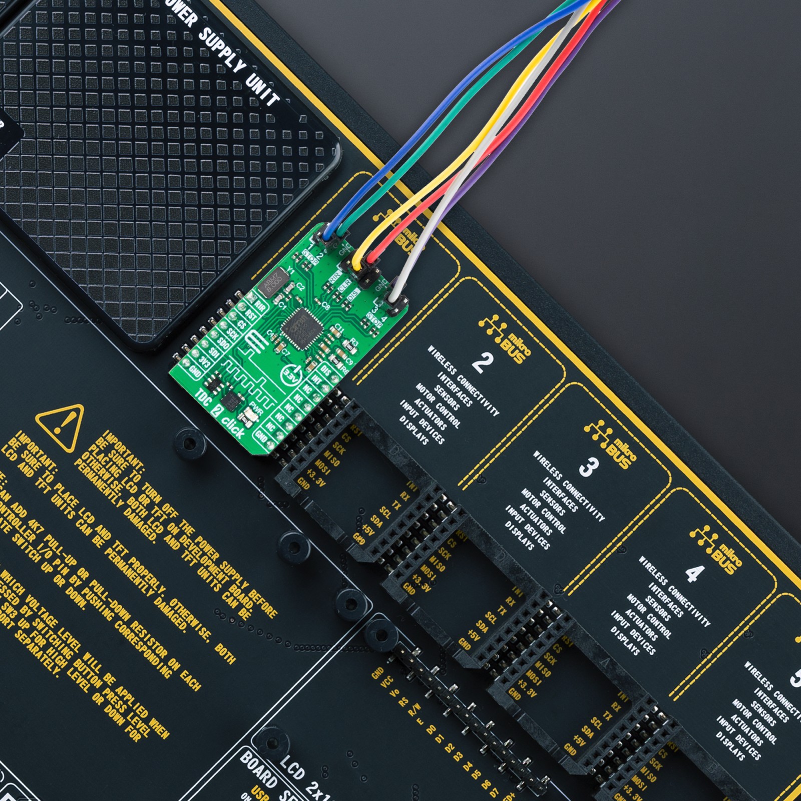
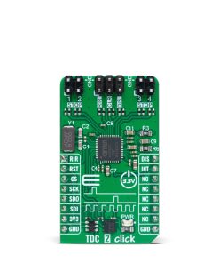
The positive edges of the stop signals, applied on the STOP terminals (1-4), are measured versus the preceding reference clock edge. The reference clock can be brought externally via the CLR pin on the middle header terminal or from the onboard 8MHz quartz oscillator. This feature is selectable through software – register-setting. The reference clock represents the framework for all time measurements and serves as a universal time base. The clock pulses are measured continuously by the TDC as a time reference point for STOP pulses and as an internal reference period. The measurement of the STOP events always refers to the preceding reference clock. Additionally, the reference clock is counted continuously, and the actual count is assigned as a reference index to a STOP pulse.
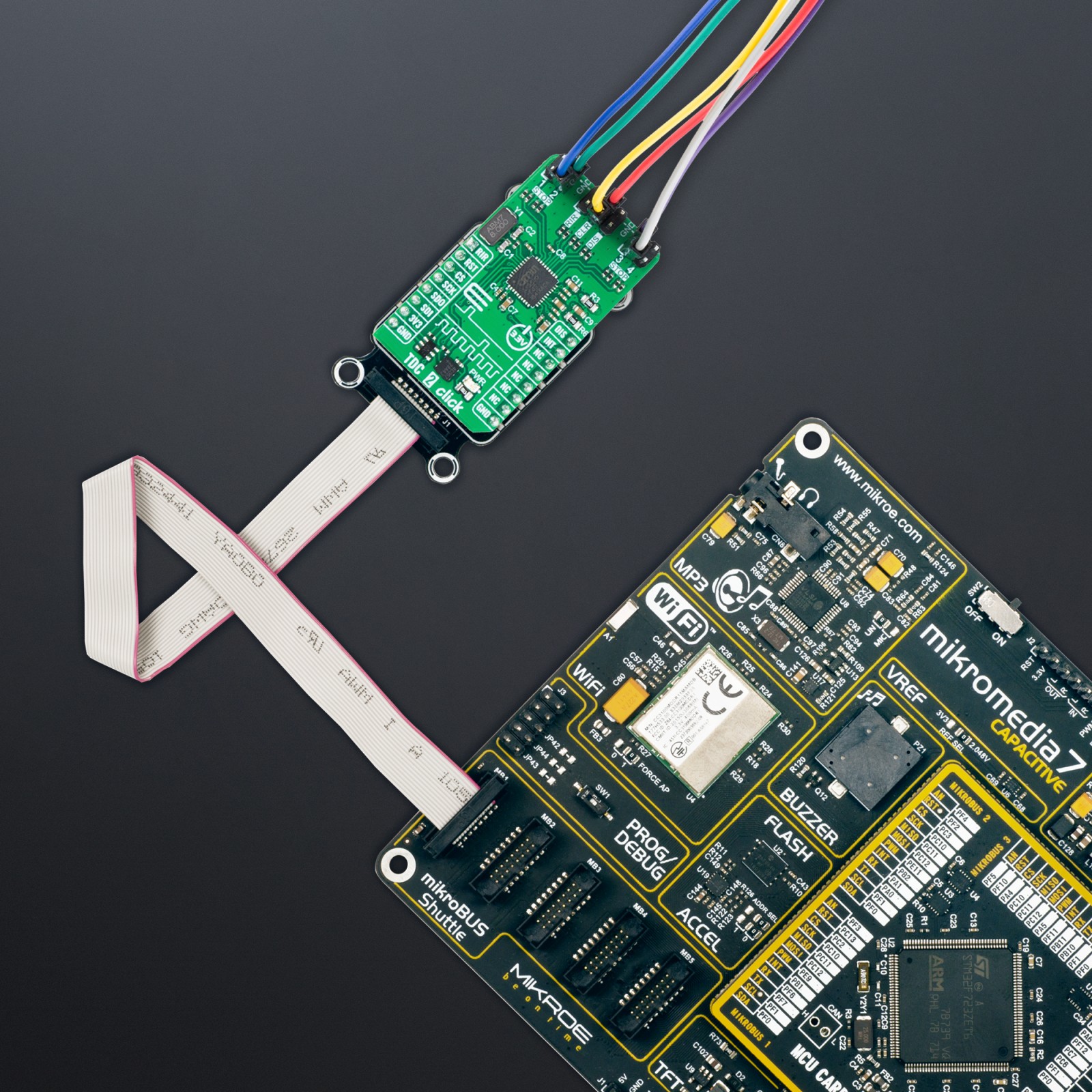
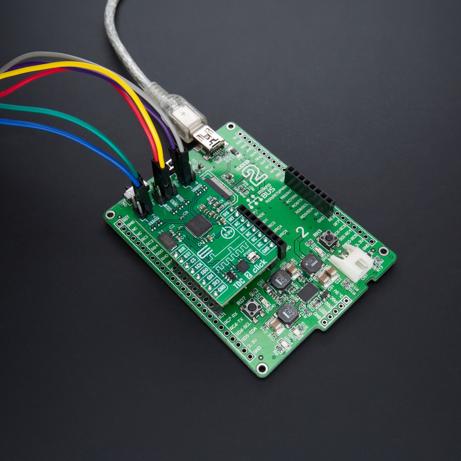
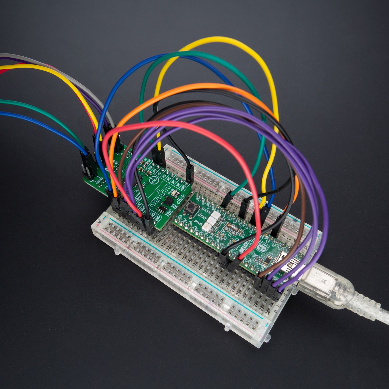
TDC 2 Click communicates with the host MCU through a standard SPI interface to read data and configure the frontend, supporting high clock speed up to 50MHz and the most common SPI mode, SPI Mode 1. Along with SPI pins, it also uses an interrupt pin that indicates to the host MCU that data are available and ready for processing.
The AS6500 uses a few more signals available on the mikroBUS™ socket for successful time measurements. With the RIR pin, the internal counter for the reference index is set back to zero, simplifying the overview of the reference index in the output data stream. Next, setting the disable pin, marked as DIS, to a high logic state, the measurements on all four stops are disabled. On the other hand, the reference clock is not affected, and internal reference measurements are continued. Apart from the mikroBUS™ socket, these signals can also be found on the middle header, grouped with the reference clock pin.
This Click board™ can only be operated from a 3.3V logic voltage level. Therefore, the board must perform appropriate logic voltage conversion before using MCUs with different logic levels. However, the Click board™ comes equipped with a library containing functions and an example code that can be used as a reference for further development.
Specifications
Type
Clock generator
Applications
Can be used general-purpose laser distance measurement in 1D, 2D, and 3D, speed control, object recognition, time-of-flight spectroscopy, and more
On-board modules
AS6500 – time-to-digital converter from ScioSense
Key Features
Simple data post-processing, high measurement performance, SPI serial interface, high data throughput, high configuration flexibility, unlimited measurement range, high resolution, and more
Interface
SPI
Feature
ClickID
Compatibility
mikroBUS™
Click board size
M (42.9 x 25.4 mm)
Input Voltage
3.3V
Pinout diagram
This table shows how the pinout on TDC 2 Click corresponds to the pinout on the mikroBUS™ socket (the latter shown in the two middle columns).
Onboard settings and indicators
Label | Name | Default | Description |
---|---|---|---|
LD1 | PWR | – | Power LED Indicator |
J1, J3 | STOP | Populated | STOP Signal Terminals |
J3 | – | Populated | Additional Time Measurement Signals Header |
TDC 2 Click electrical specifications
Description | Min | Typ | Max | Unit |
---|---|---|---|---|
Supply Voltage | – | 3.3 | – | V |
Maximum Reference Clock Frequency | – | – | 12.5 | MHz |
Software Support
We provide a library for the TDC 2 Click as well as a demo application (example), developed using Mikroe compilers. The demo can run on all the main Mikroe development boards.
Package can be downloaded/installed directly from NECTO Studio Package Manager(recommended), downloaded from our LibStock™ or found on Mikroe github account.
Library Description
This library contains API for TDC 2 Click driver.
Key functions
-
tdc2_read_results
TDC 2 results data reading function. -
tdc2_start_measuring
TDC 2 start measuring function. -
tdc2_set_resolution
TDC 2 set resolution function.
Example Description
This library contains API for TDC 2 Click driver. The library initializes and defines the SPI bus drivers to write and read data from registers, as well as the default configuration for a reading time between two STOP signals.
void application_task ( void )
{
uint32_t reference_index [ 18 ] = { 0 };
uint32_t stop_result [ 18 ] = { 0 };
uint8_t cnt = 0;
tdc2_reset_index( &tdc2 );
Delay_ms( 10 );
while ( tdc2_get_int_state( &tdc2 ) == 1 )
{
dev_generate_stop( &tdc2 );
Delay_ms( 100 );
}
while ( tdc2_get_int_state( &tdc2 ) == 0 )
{
tdc2_read_results( &tdc2, TDC2_REG_INDEX_CH1_BYTE3, &reference_index[ cnt ], &stop_result[ cnt ] );
log_printf( &logger, "CH1: Reference Index[%d]: %lu, Stop Result[%d]: %lu rn", ( uint16_t ) cnt,
reference_index[ cnt ], ( uint16_t ) cnt, stop_result[ cnt ] );
Delay_ms( 10 );
if ( cnt )
{
uint32_t time = 0;
tdc2_get_time_between_stops ( &tdc2, stop_result[ cnt - 1 ], reference_index[ cnt - 1 ],
stop_result[ cnt ], reference_index[ cnt ], &time );
log_printf( &logger, "Time between STOP %d and STOP %d is %lu ms rn",
( uint16_t ) ( cnt - 1 ), ( uint16_t ) cnt, time / TDC2_uS_TO_mS );
Delay_ms( 10 );
}
cnt++;
}
log_printf( &logger, "---------------------------------------------- rn" );
}
The full application code, and ready to use projects can be installed directly from NECTO Studio Package Manager(recommended), downloaded from our LibStock™ or found on Mikroe github account.
Other Mikroe Libraries used in the example:
- MikroSDK.Board
- MikroSDK.Log
- Click.TDC2
Additional notes and informations
Depending on the development board you are using, you may need USB UART click, USB UART 2 Click or RS232 Click to connect to your PC, for development systems with no UART to USB interface available on the board. UART terminal is available in all Mikroe compilers.
mikroSDK
This Click board™ is supported with mikroSDK – Mikroe Software Development Kit. To ensure proper operation of mikroSDK compliant Click board™ demo applications, mikroSDK should be downloaded from the LibStock and installed for the compiler you are using.
For more information about mikroSDK, visit the official page.