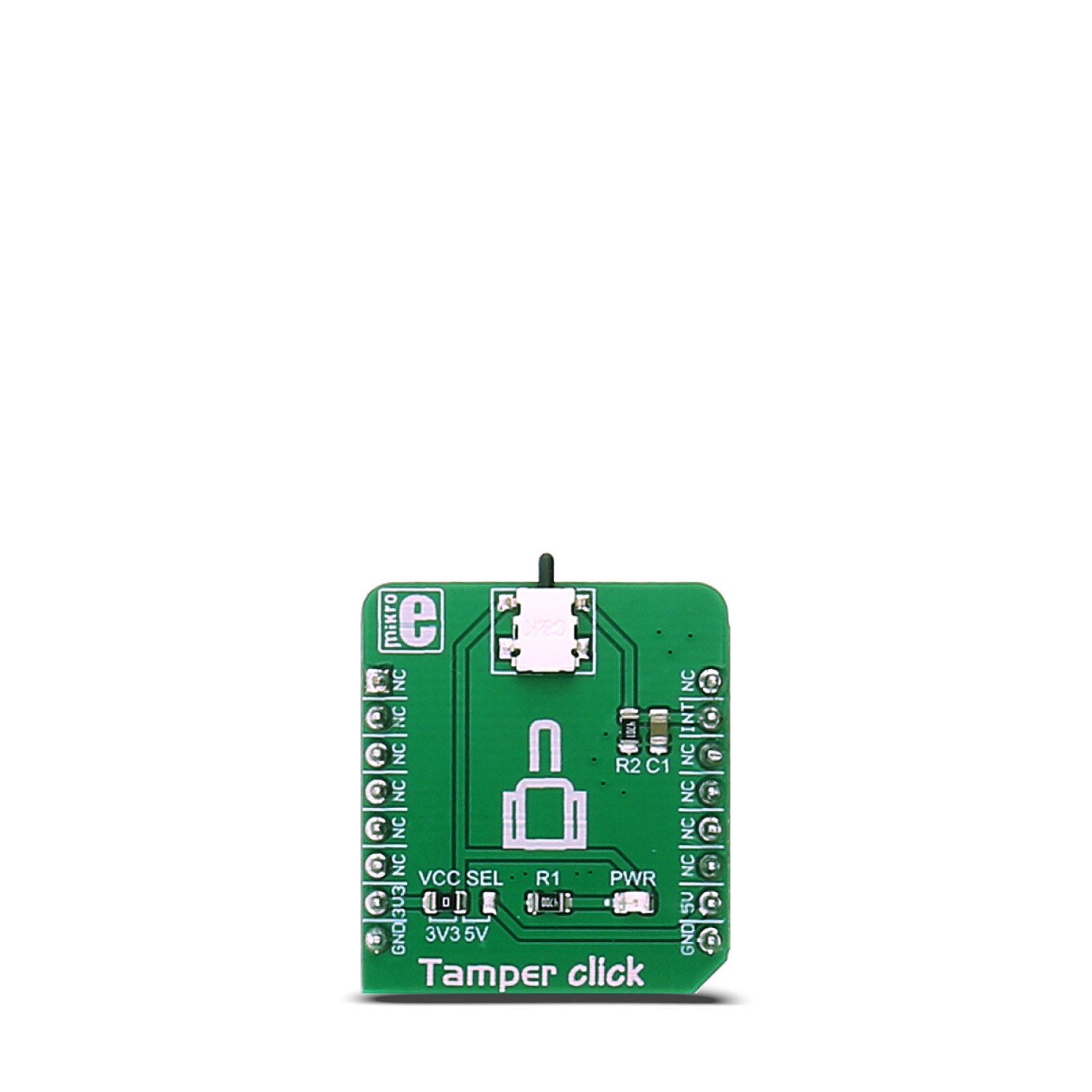
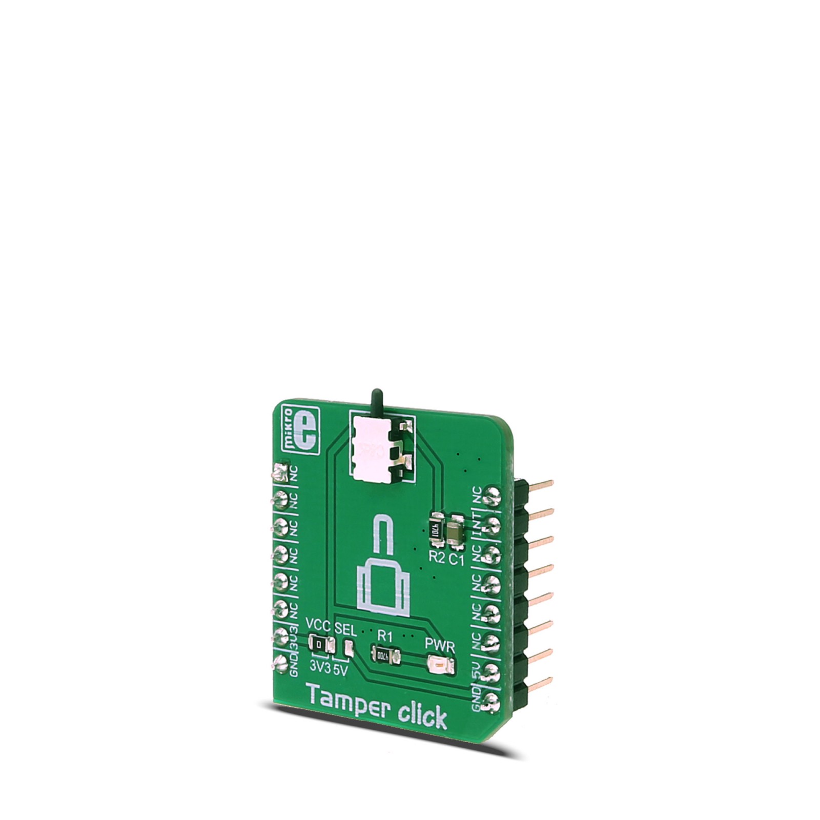
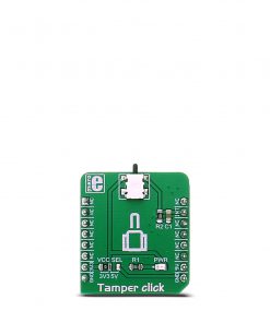
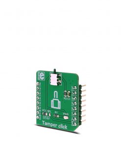
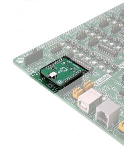
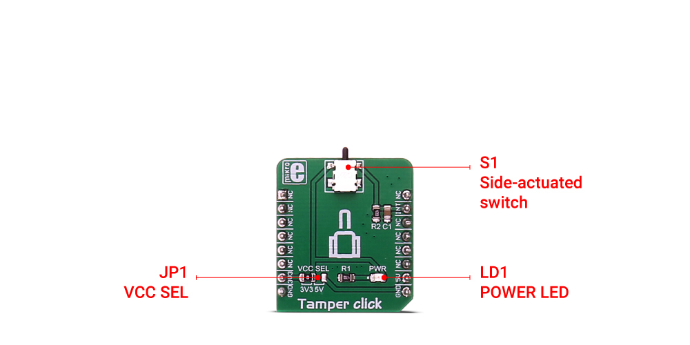
Tamper click is equipped with SDS001, a low profile side-actuated detect switch, made by C&K company. This is a high-quality, low-current detection switch, which is designed in a form of a push button. The switch itself is very small – only 2mm of switch overtravel length, which coupled with its low actuation force, makes it ideal for using it as a contact detector in various applications – consumer electronics devices, medical devices, smart card detection and similar applications.
Tamper click board™ is also additionally equipped with the RC filter that minimizes the bouncing effect, making this click a reliable solution for any contact detection application.
How does it work?
Tamper click is equipped with SDS001, low profile side-actuated detect switch. The switch itself acts as a push button and has 2 NO (Normally Open) terminals, which get shorted when the force is applied to the small piston-shaped button of the switch. These kinds of switches are usually mounted on the edge of the PCB so they can be easily reached by the elements that would apply a pressure to the switch. The applied pressure closes the circuit, connecting the VCC routed to the first pin of the switch, with the INT pin on the mikroBUS™ The microcontroller is then able to detect a high logical level on the INT pin and the desired task can then be executed. The applied RC filter serves both as a debouncing circuitry and a pull-down for the terminal of the switch, preventing the floating state that way.
The used switch itself is intended to operate with digital signal levels, thus its electrical characteristics are tailored for this purpose: low contact resistance of 100mΩ, relatively low contact ratings of 100mA at 12V and 50 000 switching cycles before the failure. These attributes make it ideal for digital signal applications, specifically.
Onboard SMD jumper allows using either 5V or 3.3V at the VCC level. This should be selected accordingly to the microcontroller pin voltage capability.
Specifications
Type
Pushbutton/Switches
Applications
Contact detector in various applications – consumer electronics devices, medical devices, smart card detection and similar applications
On-board modules
Side-actuated detect switch, made by C&K company
Key Features
Light pressure force needed to activate the switch, high number of switching cycles, optimized to be used in digital circuit
Interface
GPIO
Feature
No ClickID
Compatibility
mikroBUS™
Click board size
S (28.6 x 25.4 mm)
Input Voltage
3.3V or 5V
Pinout diagram
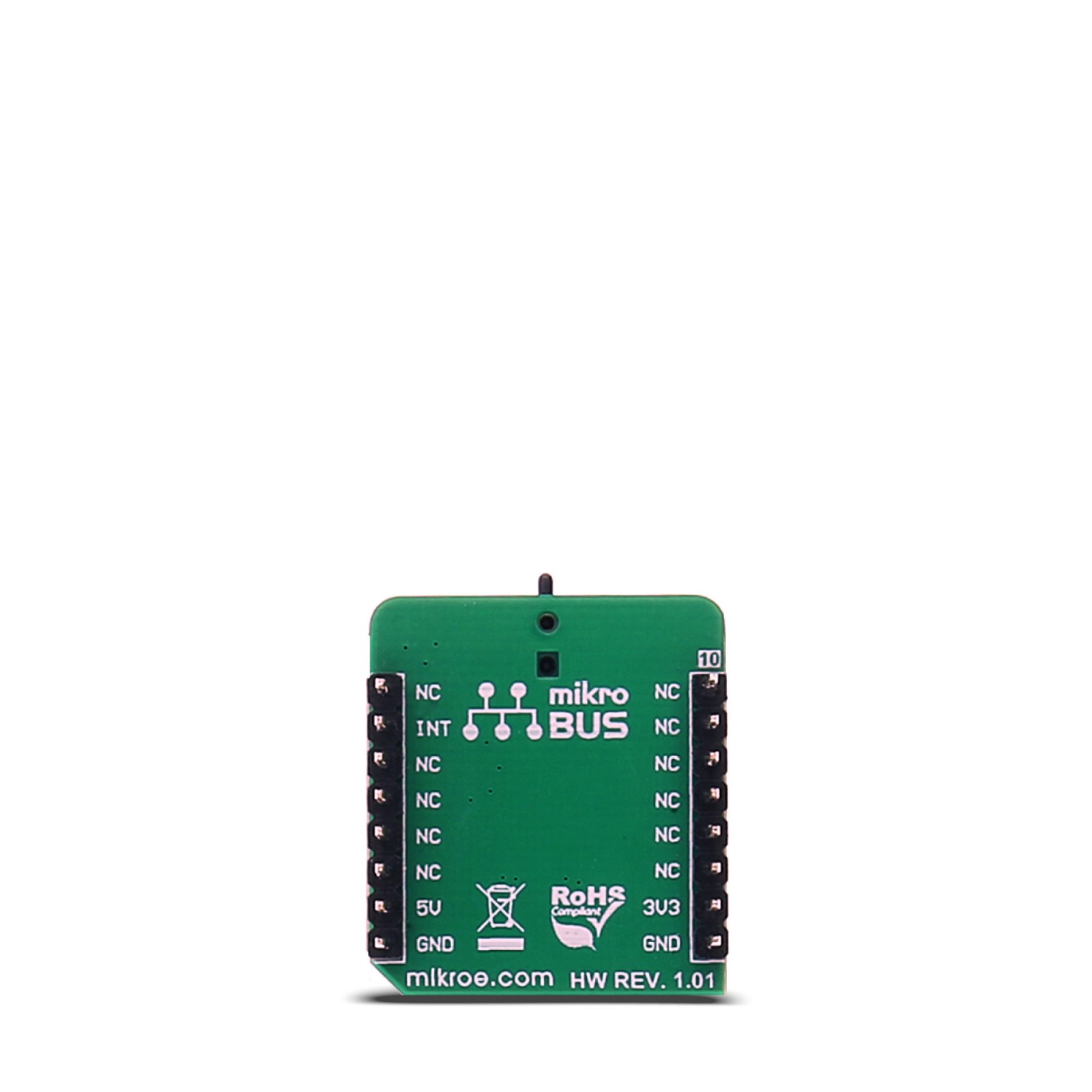
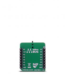
This table shows how the pinout on Tamper click corresponds to the pinout on the mikroBUS™ socket (the latter shown in the two middle columns).
Tamper click electrical specifications
Description | Min | Typ | Max | Unit |
---|---|---|---|---|
Actuation force | – | – | 75 | gr |
Contact resistance | – | – | 100 | mΩ |
Mechanical and electrical life | – | – | 50000 | cycles |
Onboard settings and indicators
Label | Name | Default | Description |
---|---|---|---|
JP1 | VCC SEL | Left | Power supply voltage selection 3V3/5V, left position 3V3, right position 5V |
S1 | SWITCH | – | The switch at the top of the click board™ |
LD1 | Power LED | – | Power LED indicates that the click is powered on |
Software support
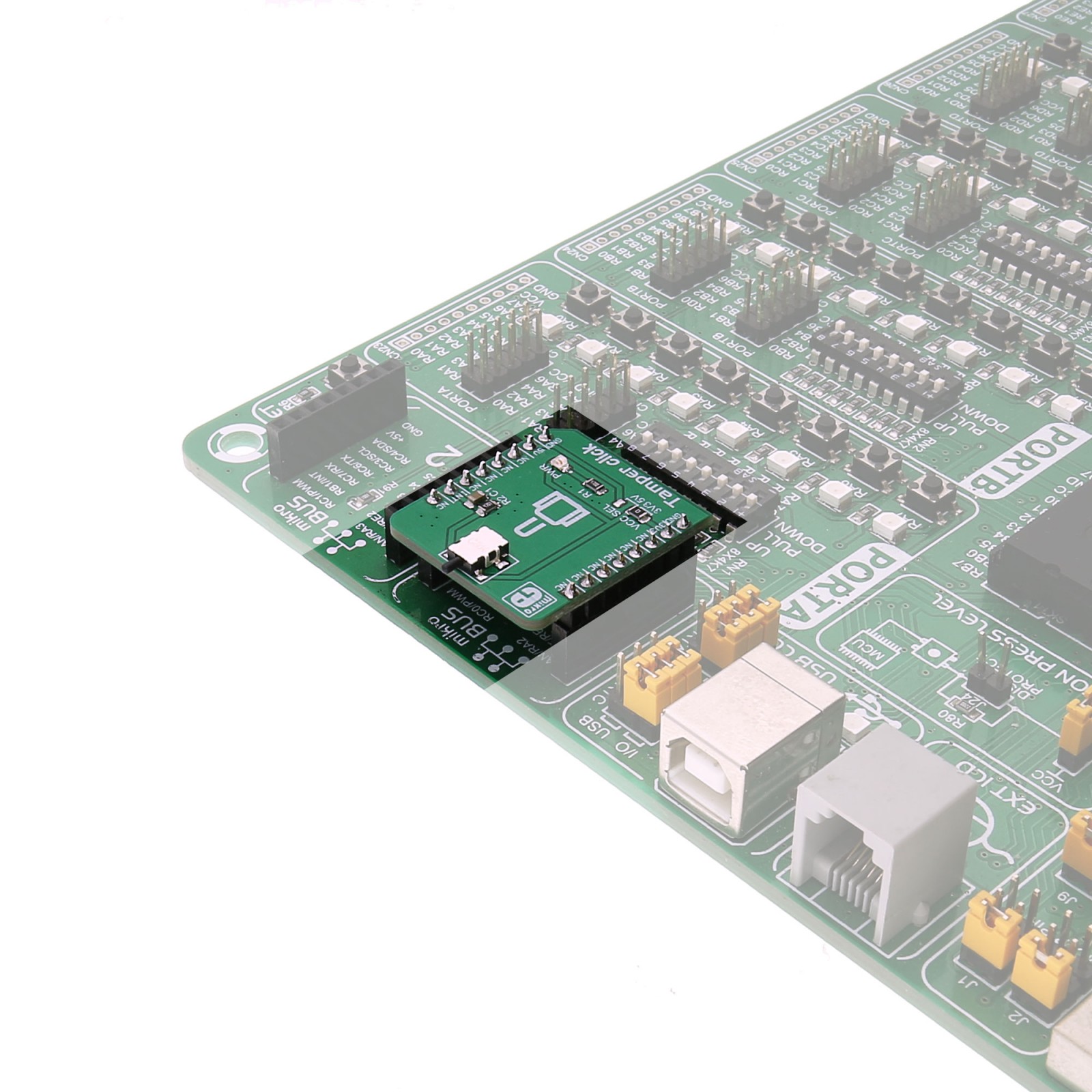
We provide an example for the Tamper click on our LibStock page, as well as a demo application (example), developed using MikroElektronika compilers. The demo can run on all the main MikroElektronika development boards.
Examples description
The application is composed of three sections:
- System initialization - Initializes the UART module used for data logging
- Application Initialization – Initializes the Tamper click GPIO pin as input
- Application task – Polls the GPIO pin and logs information to UART whenever a press is detected
Tamper_Task() { if (Tamper_STATE == 1) { UART0_Write_text("Tamper click is in ON statern"); Delay_ms(500); } }
The example code for all architectures and compilers, and ready to use projects can be found on our LibStock page.