How does it work?
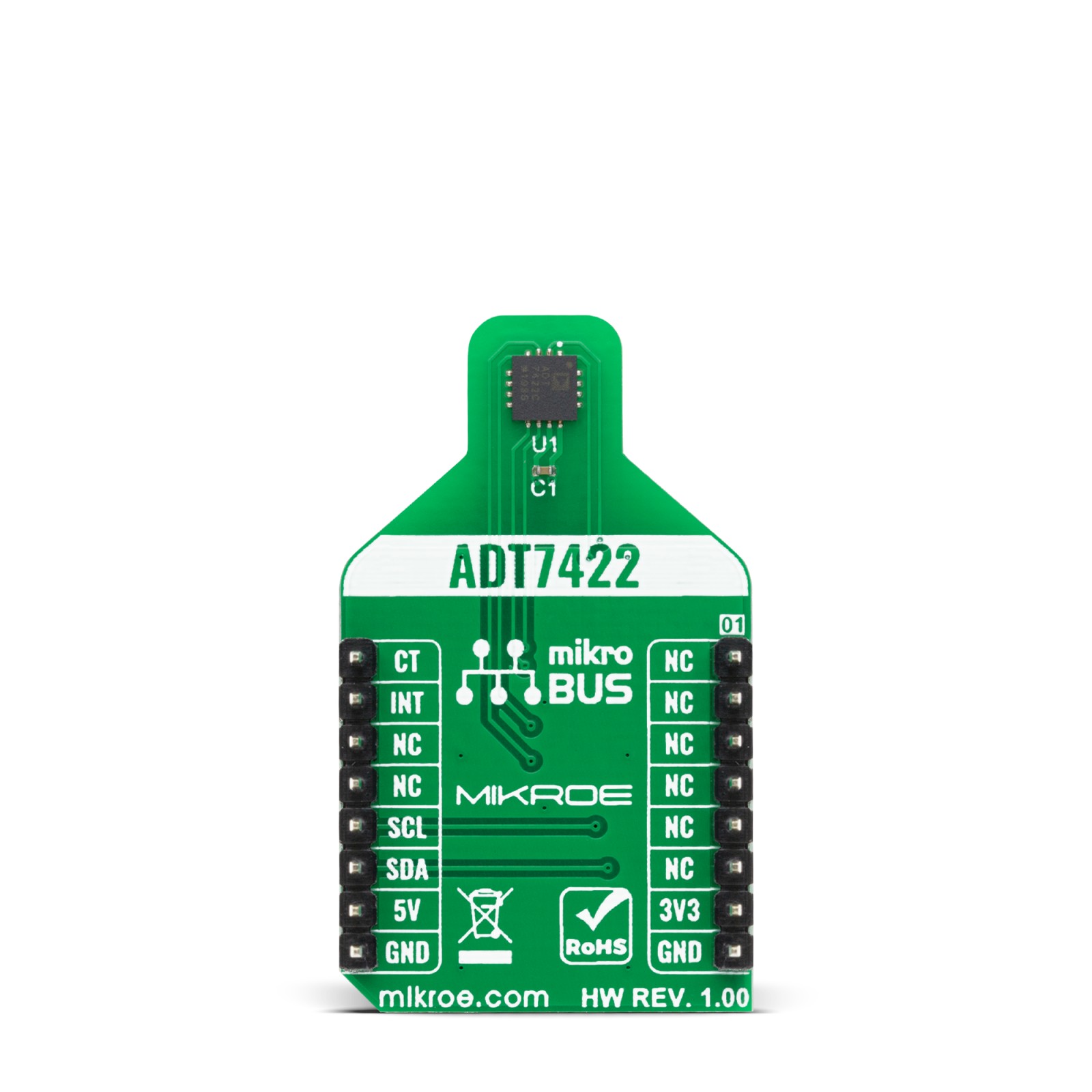
Surface temp 2 Click is based on the ADT7422, a high accuracy 16-bit digital temperature sensor with programmable interrupt and critical temperature indicator from Analog Devices. The ADT7422 has high accuracy and linearity over the entire rated temperature range without needing correction or calibration by the user. Operating at 3.3 V, the average supply current is typically 210 μA. The ADT7420 has a shutdown mode that powers down the device and offers a shutdown current of typically 2.0 μA at 3.3 V. The ADT7422 Digital Temperature Sensor is designed to meet the ASTM E1112 standard of clinical thermometry specification. This sensor is used in applications such as Vital Signs Monitoring (VSM), medical equipment, thermocouple cold junction compensation, and laser diode temperature control.
This Click board™ has a sensing pad, which is thermally connected to an ADT7422, for temperature sensing. It uses a 16-bit ADC to monitor and digitize the temperature to 0.0078°C of resolution. The ADC resolution, by default, is set to 13 bits (0.0625°C). An internal temperature sensor generates a voltage proportional to absolute temperature, which is compared to an internal voltage reference and input into a precision digital modulator. The sensor output is digitized by a Σ-Δ modulator, also known as the charge balance type ADC. This type of converter utilizes time-domain oversampling and a high accuracy comparator to deliver 16 bits of resolution.
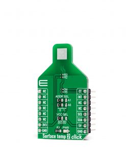
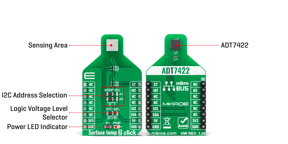
Surface temp 2 Click communicates with MCU using the standard I2C 2-Wire interface with a maximum frequency of 400kHz. The ADT7422 has a 7-bit slave address with the first five MSBs fixed to 10010. The address pins A0 and A1 are programmed by the user and determines the value of the last two LSBs of the slave address which can be selected by onboard SMD jumpers labeled as ADDR SEL allowing selection of the slave address LSBs.
It also generates a programmable interrupt signal (over/under temperature indicator) routed on the INT pin and critical overtemperature indicator CT routed on the PWM pin of the mikroBUS™ socket. Those pins have two over/under temperature modes: Comparator and Interrupt mode. The Interrupt mode is the default overtemperature mode which sets INT pin high when the temperature is greater than the internally defined limit value, while in Comparator mode the INT pin returns to an inactive state when the temperature drops below that limit value. The CT pin is activated if a critical overtemperature event occurs.
This Click board™ is designed to be operated with both 3.3V and 5V logic voltage levels that can be selected via VCC SEL jumper. This allows for both 3.3V and 5V capable MCUs to use the I2C communication lines properly.
Specifications
Type
Temperature & humidity
Applications
Can be used for RTD and thermistor replacement, medical equipment, food transportation and storage, environmental monitoring, HVAC, and other applications.
On-board modules
Surface temp 2 Click is based on the ADT7422, a high accuracy 16-bit digital temperature sensor with programmable interrupt and critical temperature indicator from Analog Devices.
Key Features
Low power consumption, no calibration needed, long-term stability and reliability, high accuracy for industrial, instrumentation, and medical applications, and more.
Interface
I2C
Feature
No ClickID
Compatibility
mikroBUS™
Click board size
M (42.9 x 25.4 mm)
Input Voltage
3.3V or 5V
Pinout diagram
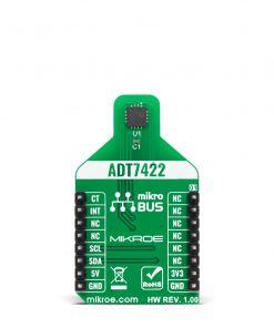
This table shows how the pinout on Surface temp 2 Click corresponds to the pinout on the mikroBUS™ socket (the latter shown in the two middle columns).
Onboard settings and indicators
Label | Name | Default | Description |
---|---|---|---|
LD1 | PWR | – | Power LED Indicator |
JP1 | VCC SEL | Left | Power Supply Voltage Selection 3V3/5V: Left position 3V3, Right position 5V |
JP2-JP3 | ADDR SEL | Left | Communication interface selection: Left position 0, Right position 1 |
Surface temp 2 Click electrical specifications
Description | Min | Typ | Max | Unit |
---|---|---|---|---|
Supply Voltage | -0.3 | – | 7 | V |
Power consumption in Normal Mode | 700 | µW | ||
Resolution | – | 16 | – | bit |
Temperature accuracy from −40°C to +125°C | -40 | – | +125 | °C |
Temperature accuracy from −40°C to +125°C | – | ±0.50 | – | °C |
Software Support
We provide a library for the Surface temp 2 Click on our LibStock page, as well as a demo application (example), developed using MikroElektronika compilers. The demo can run on all the main MikroElektronika development boards.
Library Description
The library covers all the necessary functions that enables the usage of the Surface temp 2 Click board. User can read temperature, set over temperature, under temperature, critical temperature threshold limits and hysteresis, apply different settings and perform software reset.
Key functions:
float surfacetemp2_get_temperature ( );
– Function is used to read and calculate temperatre value.uint8_t surfacetemp2_setup ( uint8_t setup );
– Function is used to apply the desired settings.void surfacetemp2_set_hys_val ( uint8_t hys_val );
– Function is used to set hysteresis.
Examples description
The application is composed of three sections :
- System Initialization – Initializes I2C and LOG, and sets INT and PWM pins as input.
- Application Initialization – Initalizes I2C driver and sets up the device.
- Application Task – This example shows capabilities of Surface temp 2 Click board by reading temperature and displaying the results via USART terminal.
void application_task ( ) { temperature = surfacetemp2_get_temperature( ); FloatToStr( temperature, log_txt ); mikrobus_logWrite( " Temperature : ", _LOG_TEXT ); mikrobus_logWrite( log_txt, _LOG_TEXT ); mikrobus_logWrite( " °C", _LOG_LINE ); Delay_ms( 2000 ); }
The full application code, and ready to use projects can be found on our LibStock page.
Other mikroE Libraries used in the example:
- I2C
- UART
- Conversions
Additional notes and informations
Depending on the development board you are using, you may need USB UART click, USB UART 2 click or RS232 click to connect to your PC, for development systems with no UART to USB interface available on the board. The terminal available in all MikroElektronika compilers, or any other terminal application of your choice, can be used to read the message.
mikroSDK
This Click board™ is supported with mikroSDK – MikroElektronika Software Development Kit. To ensure proper operation of mikroSDK compliant Click board™ demo applications, mikroSDK should be downloaded from the LibStock and installed for the compiler you are using.
For more information about mikroSDK, visit the official page.