How does it work?
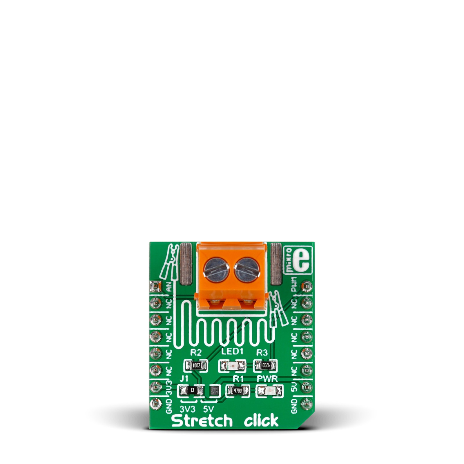
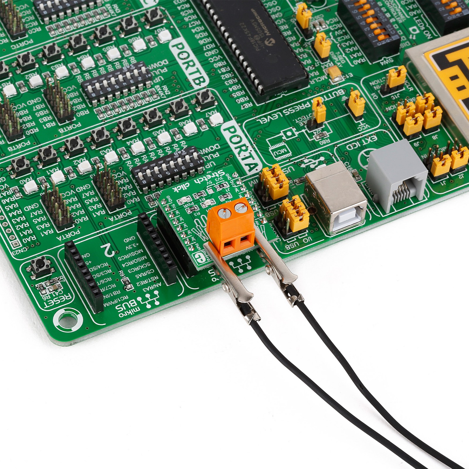
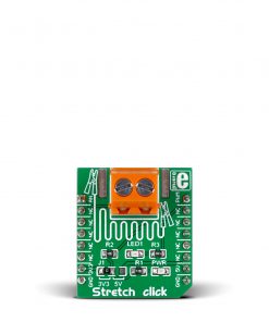
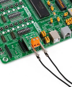
Stretch Click is based on the circuitry that allows measuring the stretch forces of the 2mm diameter conductive rubber cord. In a “relaxed” state, the resistance is about 130 ohms per centimeter. The resistance increases as you stretch it out (the particles get further apart); for example, a 15cm piece is proportional to 2.1k ohms (25cm long stretch is 26/15*2.1K = 3.5k ohms). You can stretch the rubber about 50-70% longer than the resting length, so a 15cm piece shouldn’t be stretched more than 25cm. Once the force is released, the rubber will shrink back, although it’s not very “fast” and it takes a minute or two to revert to its original length.
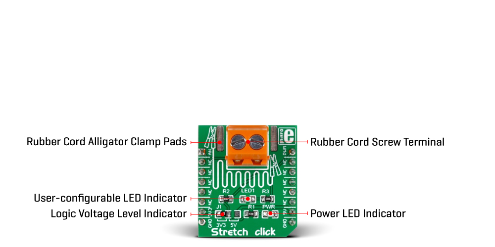
The resistance of the cord increases when stretched, impacting the reverse voltage on the voltage divider, which can be measured. The Stretch Click allows stretch force readings to be available on an analog AN pin of the mikroBUS™ socket. It’s not a true linear sensor, and the resistance may vary from batch to batch, so we consider it a way to measure stretching motion, but it isn’t really precise. In addition, this Click board™ features a user-configurable LED1 light-emitting diode that can visually represent the measured force. This LED1 can be controlled over the PWM pin of the mikroBUS™ socket.
This Click board™ can operate with either 3.3V or 5V logic voltage levels selected via the J1 jumper. This way, both 3.3V and 5V capable MCUs can use the communication lines properly. However, the Click board™ comes equipped with a library containing easy-to-use functions and an example code that can be used, as a reference, for further development.
Specifications
Type
Force
Applications
Can be used for development of applications that needs the stretch force data readings
On-board modules
Circuitry for measuring stretch forces with conductive rubber cords
Key Features
Measuring the stretch forces of the 2mm diameter conductive rubber cord, rubber cord with 140-160 ohms per centimeter resistance included, screw terminal with copper exposed pads, analog representation of stretch force, user-configurable LED, and more
Interface
Analog,PWM
Feature
No ClickID
Compatibility
mikroBUS™
Click board size
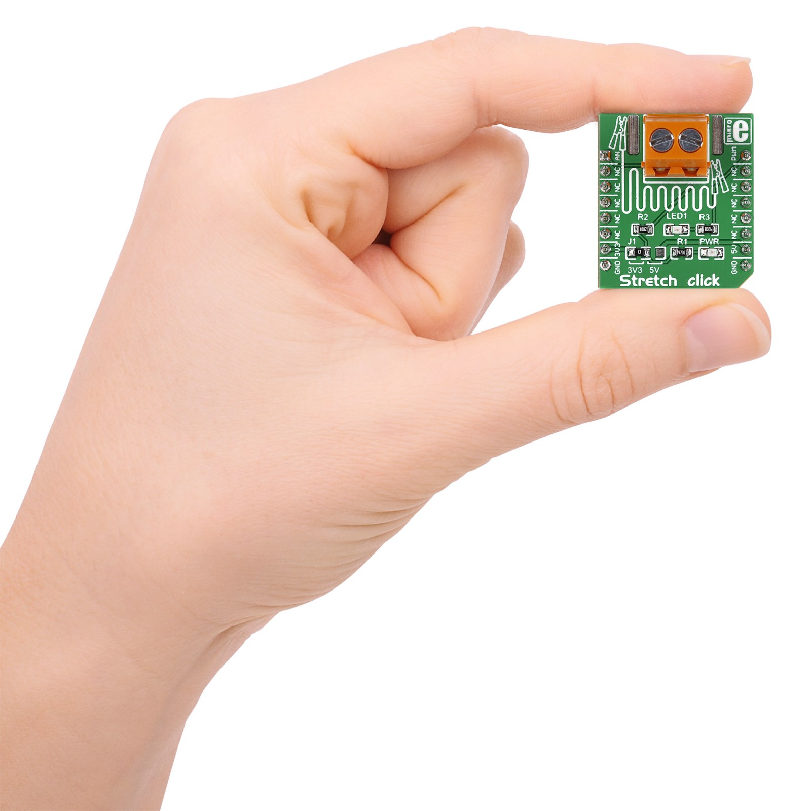
S (28.6 x 25.4 mm)
Input Voltage
3.3V or 5V
Pinout diagram
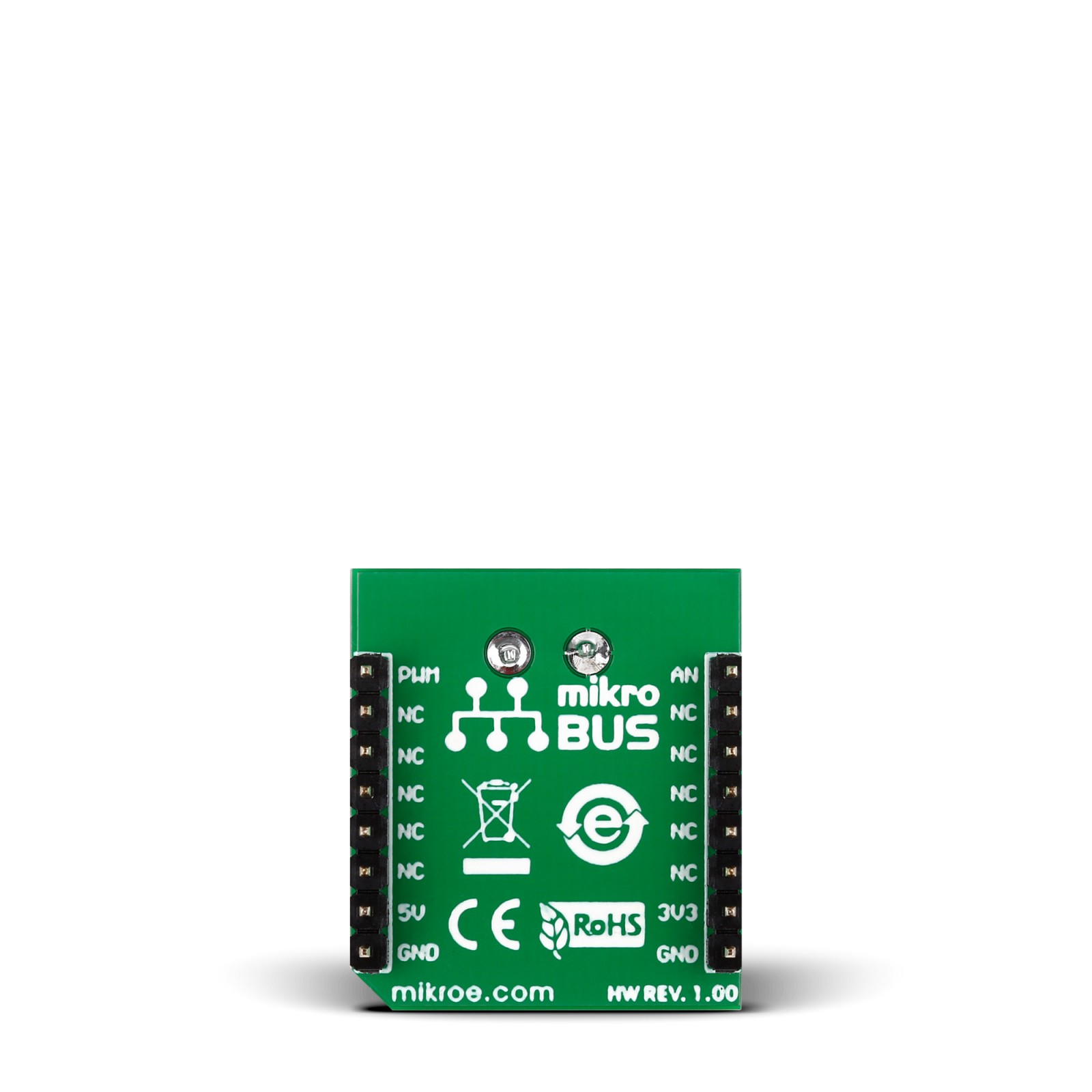
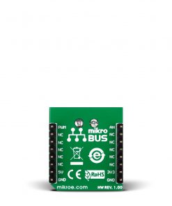
This table shows how the pinout on Stretch Click corresponds to the pinout on the mikroBUS™ socket (the latter shown in the two middle columns).
Onboard settings and indicators
Label | Name | Default | Description |
---|---|---|---|
– | PWR | – | Power LED Indicator |
– | LED1 | – | User Configurable LED Indicator |
JP1 | 3V3 5V | Left | Logic Level Voltage Selection 3V3/5V: Left position 3V3, Right position 5V |
Stretch Click electrical specifications
Description | Min | Typ | Max | Unit |
---|---|---|---|---|
Supply Voltage | 3.3 | – | 5 | V |
Conductive Rubber Cord Diameter | – | 2 | – | mm |
Software Support
We provide a library for the Stretch Click as well as a demo application (example), developed using MIKROE compilers. The demo can run on all the main MIKROE development boards.
Package can be downloaded/installed directly from NECTO Studio Package Manager (recommended), downloaded from our LibStock™ or found on MIKROE github account.
Library Description
This library contains API for Stretch Click driver.
Key functions
-
Config Object Initialization function.
-
Turn on the LED function
-
Turn off the LED function
Example Description
The application is for stretch measuring
void application_task ( void )
{
stretch_data_t tmp;
// Task implementation.
tmp = stretch_generic_read ( &stretch );
log_printf( &logger, "** ADC value : [DEC]- %d, [HEX]- 0x%x rn", tmp, tmp );
Delay_ms( 1000 );
Delay_100ms( );
if ( tmp < 500 )
{
stretch_turn_on_led( &stretch );
}
else
{
stretch_turn_off_led( &stretch );
}
log_printf( &logger, " Resistance : %d rn", tmp );
log_printf( &logger, "-------------------" );
Delay_1sec( );
}
The full application code, and ready to use projects can be installed directly from NECTO Studio Package Manager (recommended), downloaded from our LibStock™ or found on MIKROE github account.
Other MIKROE Libraries used in the example:
- MikroSDK.Board
- MikroSDK.Log
- Click.Stretch
Additional notes and informations
Depending on the development board you are using, you may need USB UART click, USB UART 2 Click or RS232 Click to connect to your PC, for development systems with no UART to USB interface available on the board. UART terminal is available in all MIKROE compilers.
mikroSDK
This Click board™ is supported with mikroSDK – MIKROE Software Development Kit. To ensure proper operation of mikroSDK compliant Click board™ demo applications, mikroSDK should be downloaded from the LibStock and installed for the compiler you are using.
For more information about mikroSDK, visit the official page.