How does it work?
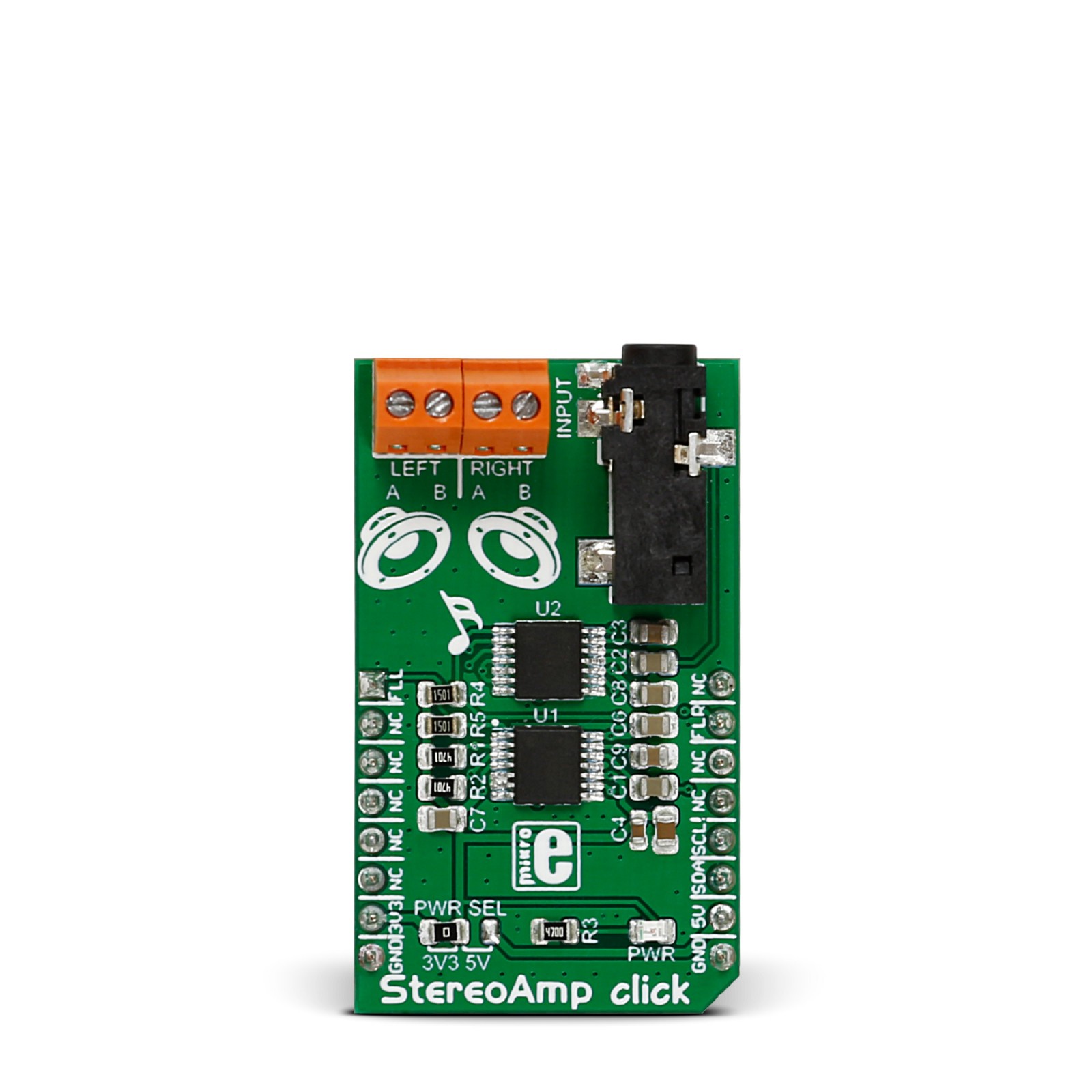
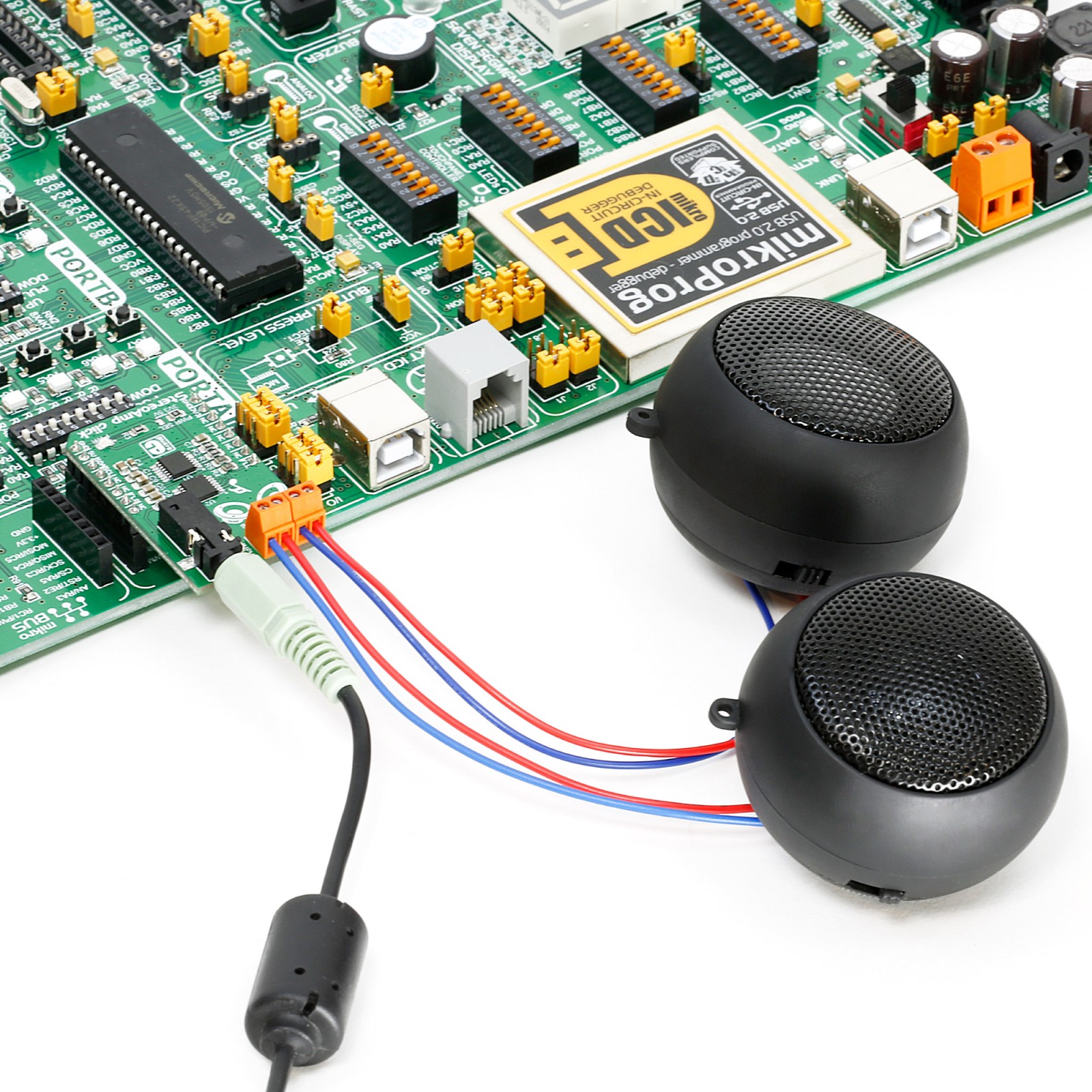
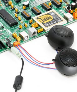
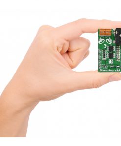
StereoAmp Click is based on two LM48100Qs, Boomer mono audio power amplifiers with output fault detection and volume control from Texas Instruments. The inputs of the amplifiers can be mixed/multiplexed to the device’s outputs. Each input has its own independent 32-step volume control. Each amplifier has short circuit and thermal protection, advanced click-and-pop suppression, and high PSRR. The StereoAmp Click features a 3.5mm audio jack as input and two pairs of screw terminals as output for connecting passive speakers. Each amplifier is used for one channel, left or right.
The amplifiers are designed to drive a load differentially, a configuration better known as a bridge-tied load (BTL). BTL is an output configuration where the speakers are connected (bridged) between two audio amplifier outputs. In a single-ended configuration, one side of the load is connected to the ground. Here both channels are connected, but one has an inverted signal. Compared to a single-ended configuration, BTL has two times more voltage swing across the load (speakers). The doubled voltage swing means four times more power to the speakers. This is ideal for applications and devices where the supply voltage is lower due to battery size.
The output fault detection system can sense load conditions, protect the device during short circuit events, and detect open circuit conditions. The LM48100Q-Q1 output fault diagnostics are controlled through the I2C interface. In addition, the IC has an I2C selectable low-power shutdown mode that turns off the device, reducing current consumption to 0.01μA.
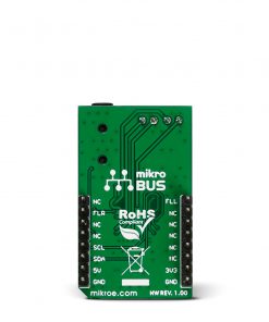
The StereoAmp Click uses the standard write-only 2-Wire I2C interface to communicate with the host MCU, supporting clock rates up to 400KHz. There are two fault detection pins, labeled FLL and FLR, according to a left or right channel. Those pins will go logic LOW if the fault condition occurs.
This Click board™ can operate with either 3.3V or 5V logic voltage levels selected via the PWR SEL jumper. This way, both 3.3V and 5V capable MCUs can use the communication lines properly. However, the Click board™ comes equipped with a library containing easy-to-use functions and an example code that can be used, as a reference, for further development.
Specifications
Type
Amplifier
Applications
Can be used for the development of automotive audio devices, hands-free kits, battery-operated devices, computers, MP3 players, and more
On-board modules
LM48100Q – BoomerTM mono audio power amplifiers with output fault detection and volume control from Texas Instruments
Key Features
Screw terminals for speaker output, individual 32-step volume control, output fault detection for both channels, low-power shutdown mode, short circuit, and thermal protection, advanced click-and-pop suppression, high PSRR, and more
Interface
GPIO,I2C
Feature
No ClickID
Compatibility
mikroBUS™
Click board size
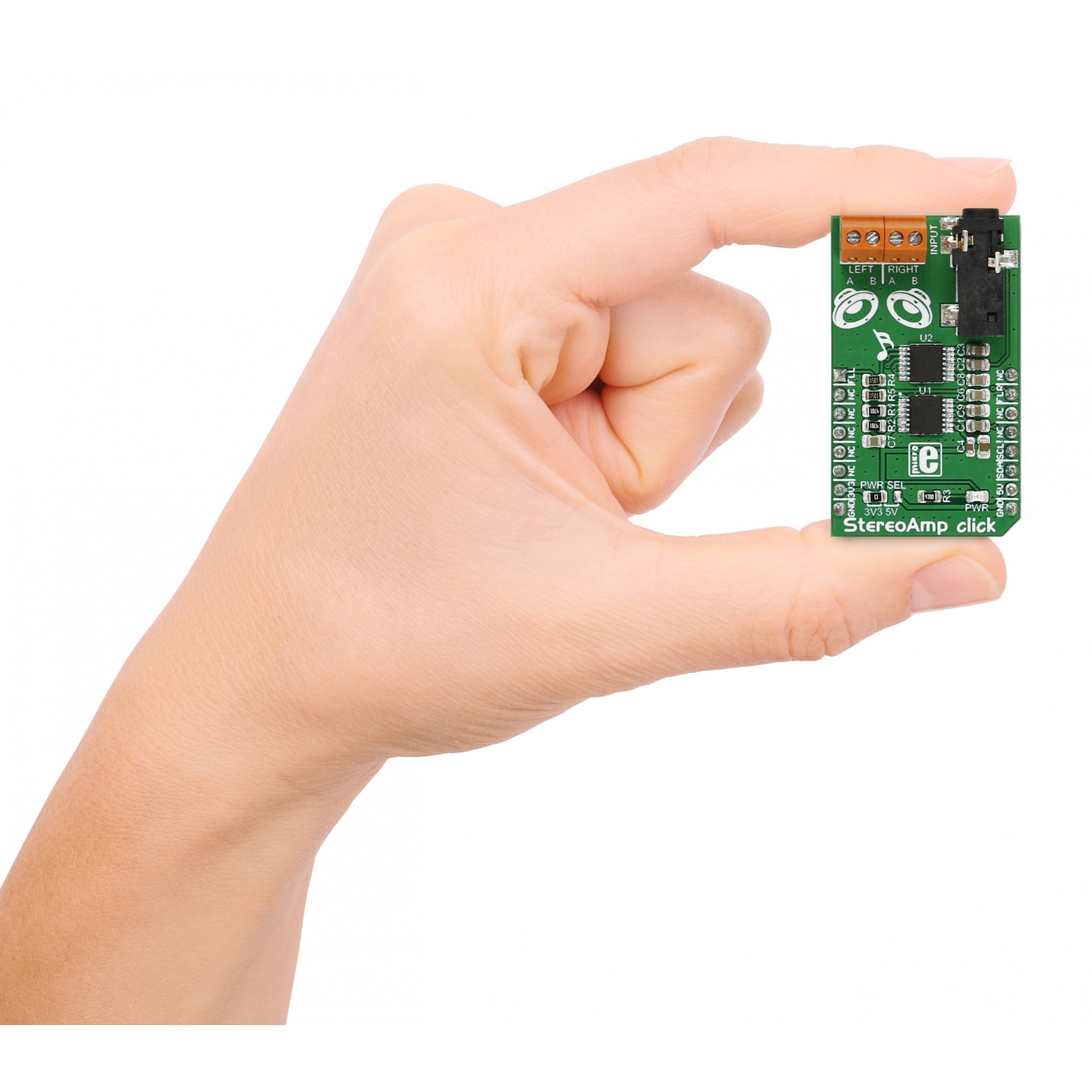
M (42.9 x 25.4 mm)
Input Voltage
3.3V or 5V
Pinout diagram
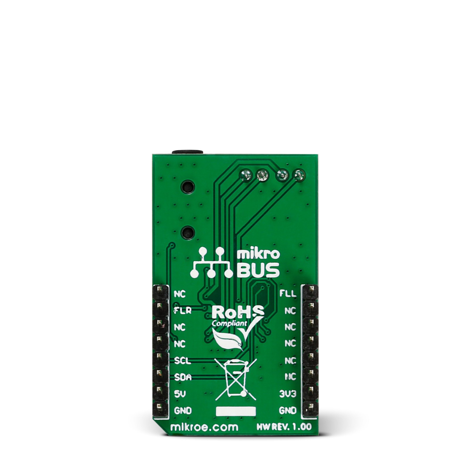
This table shows how the pinout on StereoAmp click corresponds to the pinout on the mikroBUS™ socket.
Onboard settings and indicators
Label | Name | Default | Description |
---|---|---|---|
LD1 | PWR | – | Power LED Indicator |
JP1 | PWR SEL | Left | Power/Logic Level Voltage Selection 3V3/5V: Left position 3V3, Right position 5V |
StereoAmp Click electrical specifications
Description | Min | Typ | Max | Unit |
---|---|---|---|---|
Supply Voltage | 3.3 | – | 5 | V |
Output Power @5V | – | – | 1.3 | W |
Load Resistance | – | 8 | – | Ω |
Software Support
We provide a library for the StereoAmp Click as well as a demo application (example), developed using MIKROE compilers. The demo can run on all the main MIKROE development boards.
Package can be downloaded/installed directly from NECTO Studio Package Manager (recommended), downloaded from our LibStock™ or found on Mikroe github account.
Library Description
This library contains API for StereoAmp Click driver.
Key functions
-
This function set the power On of both channels by write to the Mode Control register address of LM48100Q-Q1 chip on StereoAmp click board.
-
This function set the volume of both channels to the Volume Control register address of LM48100Q-Q1 chip on StereoAmp click board.
Example Description
This example shows how to initialize amplifiers and set volume control registers on the fly.
void application_task ( void )
{
log_printf( &logger, " Gain 1.5 dB rn" );
stereoamp_set_volume( &stereoamp, STEREOAMP_GAIN_1_5dB );
Delay_ms ( 10000 );
log_printf( &logger, "--------------------------rn" );
log_printf( &logger, " Gain -13.5 dB rn" );
stereoamp_set_volume( &stereoamp, STEREOAMP_GAIN_NEG_13_5dB );
Delay_ms ( 10000 );
log_printf( &logger, "--------------------------rn" );
}
The full application code, and ready to use projects can be installed directly from NECTO Studio Package Manager (recommended), downloaded from our LibStock™ or found on Mikroe github account.
Other Mikroe Libraries used in the example:
- MikroSDK.Board
- MikroSDK.Log
- Click.StereoAmp
Additional notes and informations
Depending on the development board you are using, you may need USB UART click, USB UART 2 Click or RS232 Click to connect to your PC, for development systems with no UART to USB interface available on the board. UART terminal is available in all MIKROE compilers.
mikroSDK
This Click board™ is supported with mikroSDK – MIKROE Software Development Kit. To ensure proper operation of mikroSDK compliant Click board™ demo applications, mikroSDK should be downloaded from the LibStock and installed for the compiler you are using.
For more information about mikroSDK, visit the official page.