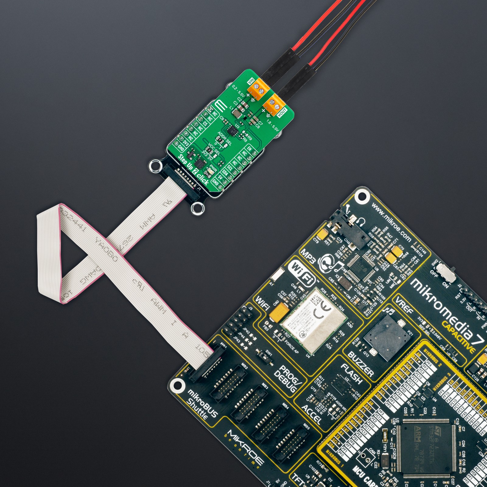
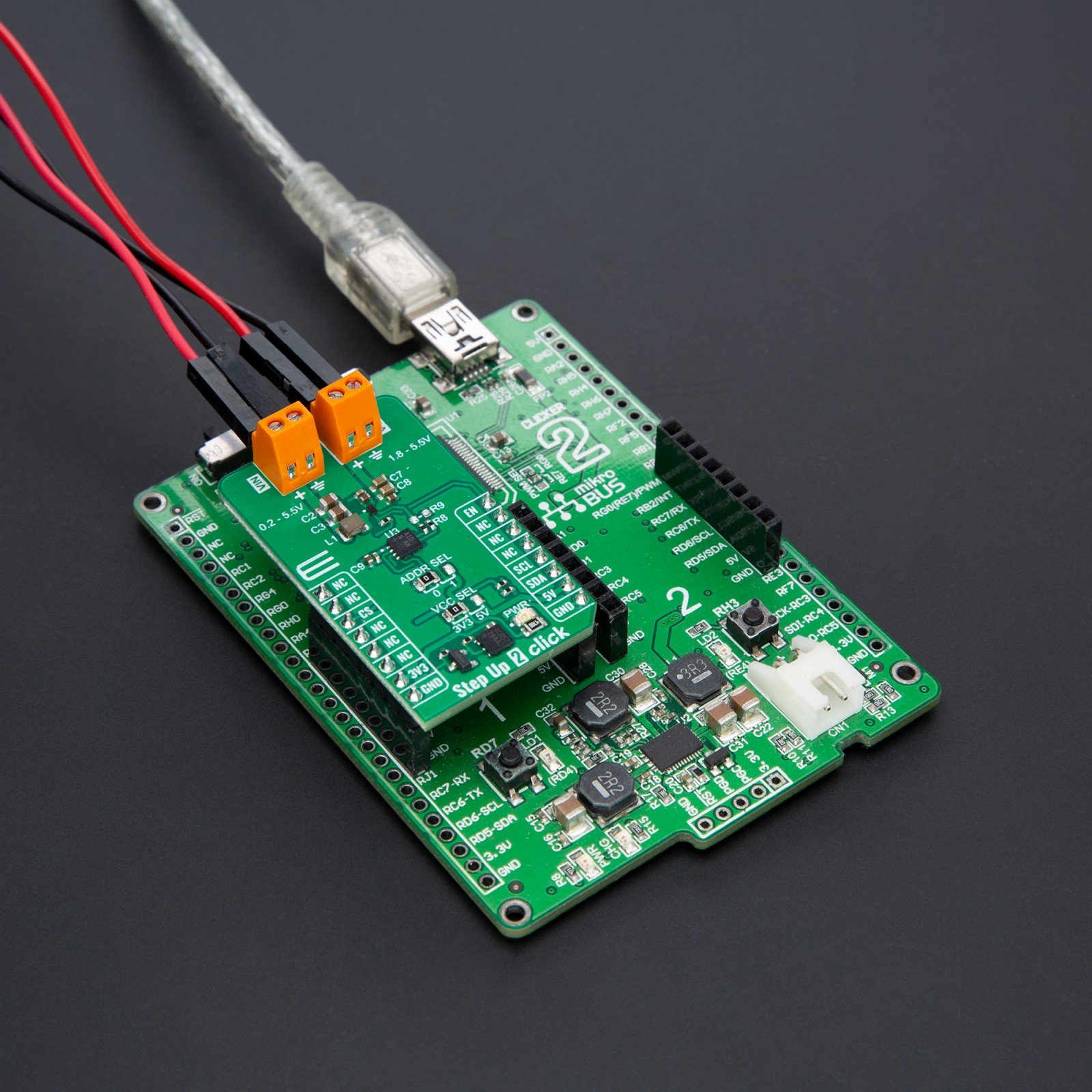
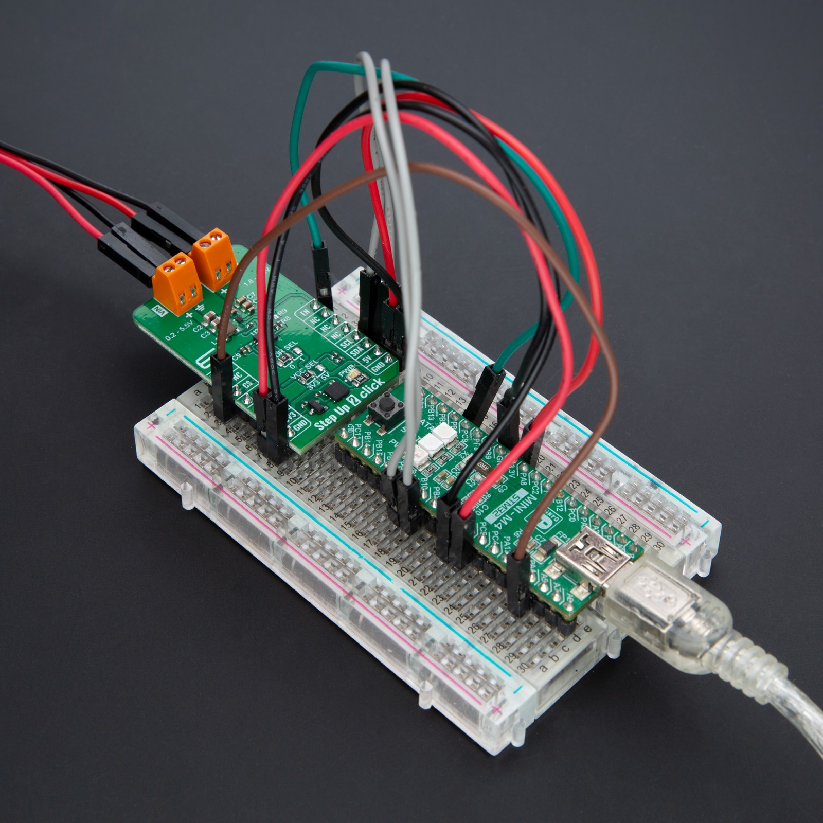
How does it work?
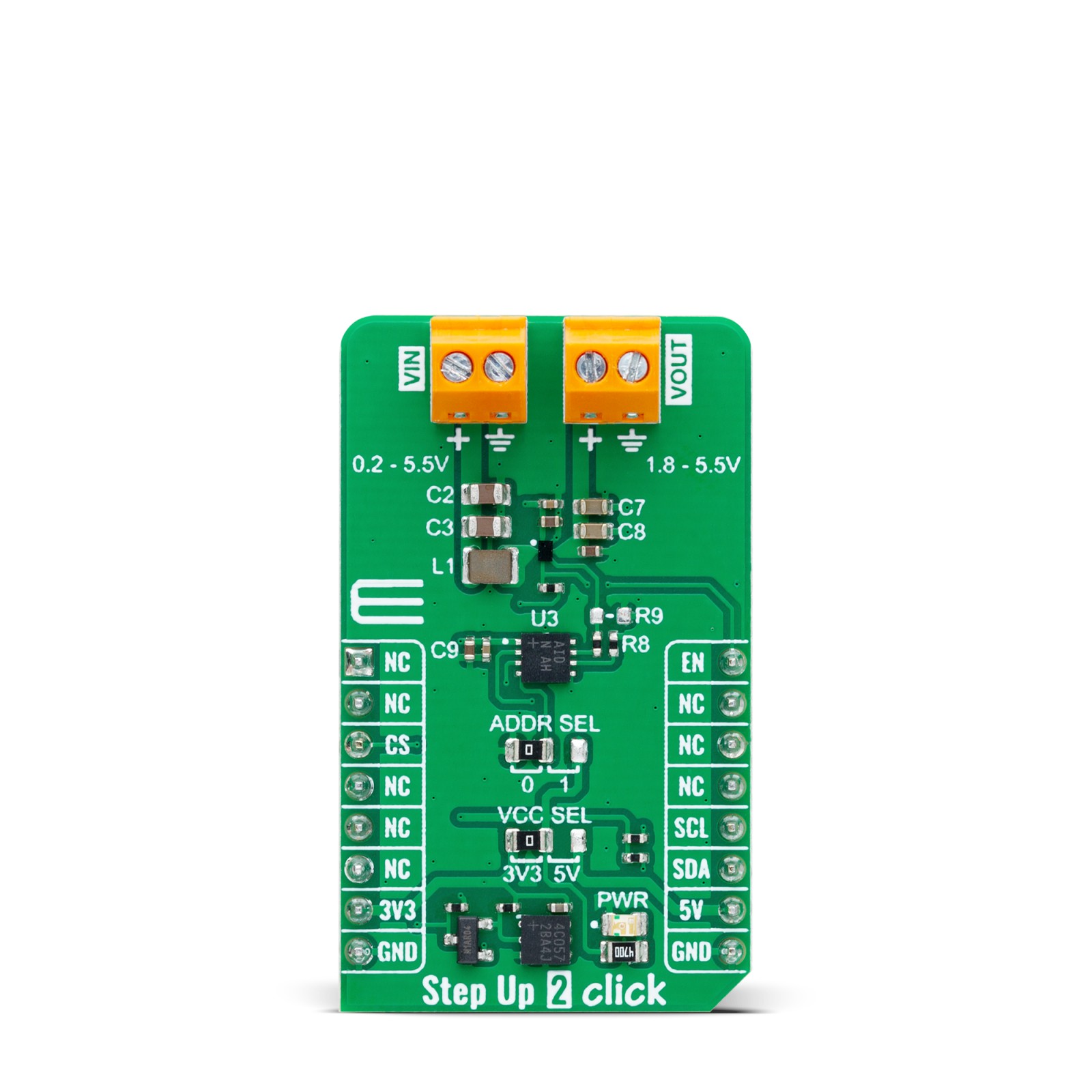
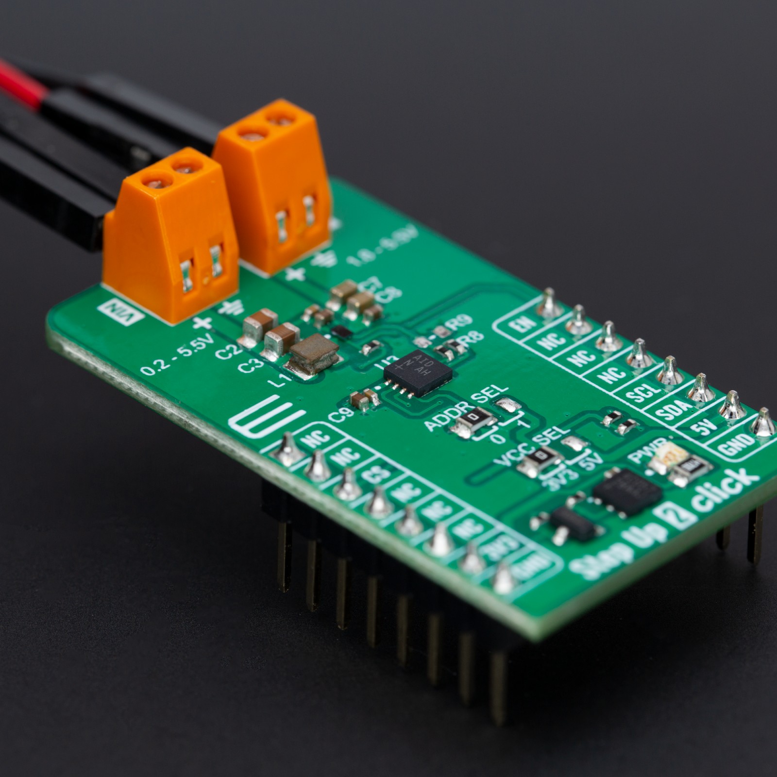
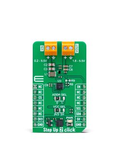
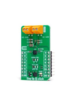
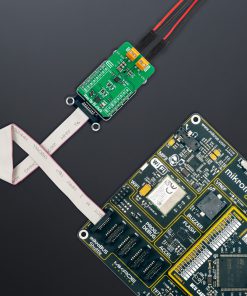
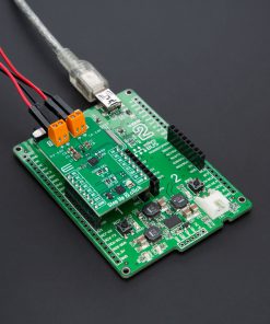
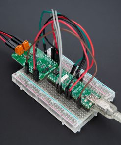
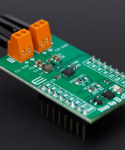
Step Up 2 Click is based on the TPS61299, a synchronous boost converter with an exceptionally low quiescent current from Texas Instruments. It is designed to provide efficient power solutions for devices powered by alkaline or coin cell batteries, boasting high efficiency even under light-load conditions to extend operational time. This component also stands out for its additional current limit functionality, ensuring optimal performance and reliability. With the ability to operate by simply using the EN pin from the mikroBUS™ socket for device enablement – a high logic signal activates the device, whereas a low logic signal deactivates it—this boost converter exemplifies efficiency and ease of use.
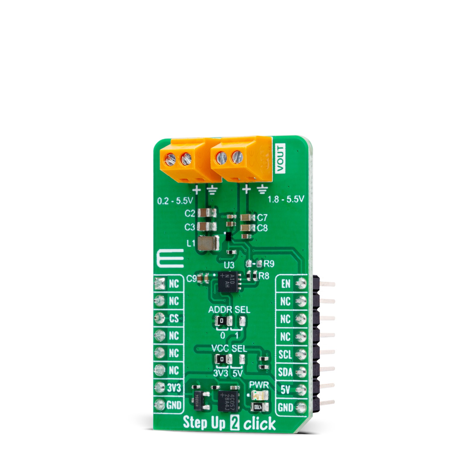
The Step Up 2 Click also integrates the MAX5419, a digital potentiometer from Analog Devices, for precise output voltage adjustments, as well as ADDR SEL jumper. This jumper allows for seamless selection of the I2C address of the MAX5419, leveraging the I2C interface for meticulous control. Supplying an external voltage range from 0.2V to 5.5V via the VIN terminal, the board offers a regulated output voltage range from 1.8V to 5.5V at the VOUT terminal – adjustable through digital potentiometer configuration.
This Click board™ can operate with either 3.3V or 5V logic voltage levels selected via the VCC SEL jumper. This way, both 3.3V and 5V capable MCUs can use the communication lines properly. Also, this Click board™ comes equipped with a library containing easy-to-use functions and an example code that can be used as a reference for further development.
Specifications
Type
Boost
Applications
Ideal for portable electronics, wearables, and small-scale IoT devices
On-board modules
TPS61299 – synchronous boost converter from Texas Instruments
Key Features
Adjustable output voltage, ultra-low quiescent current, high efficiency, fast transient performance, low power consumption, logic for MCU compatibility, and more
Interface
GPIO,I2C
Feature
ClickID
Compatibility
mikroBUS™
Click board size
M (42.9 x 25.4 mm)
Input Voltage
3.3V or 5V,External
Pinout diagram
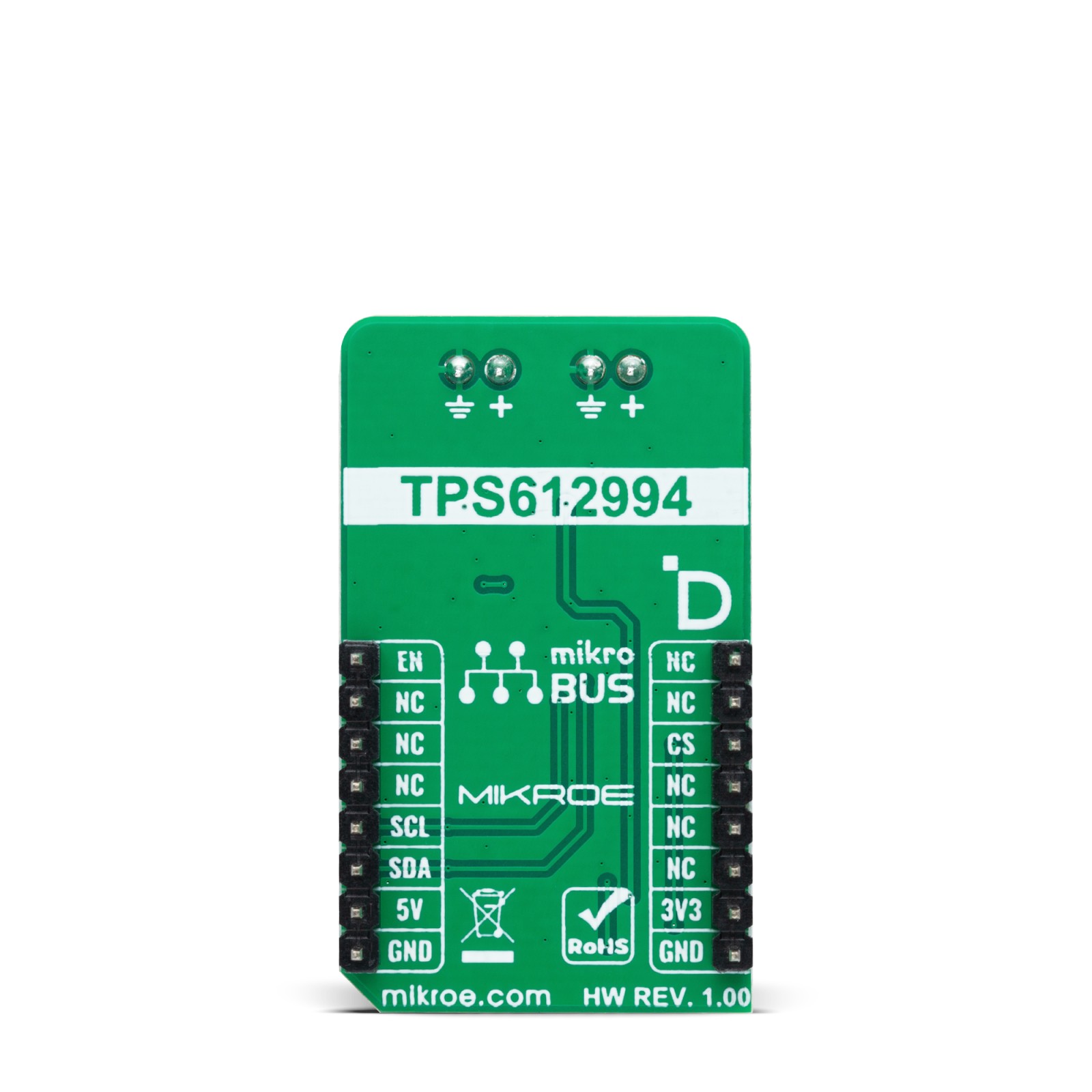
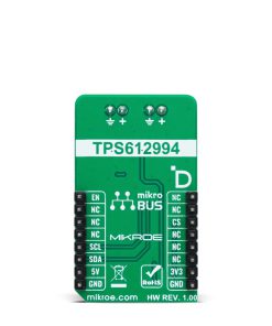
This table shows how the pinout on Step Up 2 Click corresponds to the pinout on the mikroBUS™ socket (the latter shown in the two middle columns).
Onboard settings and indicators
Label | Name | Default | Description |
---|---|---|---|
LD1 | PWR | – | Power LED Indicator |
JP1 | VCC SEL | Left | Power Voltage Level Selection 3V3/5V: Left position 3V3, Right position 5V |
JP2 | ADDR SEL | Left | I2C Address Selection 0/1: Left position 0, Right position 1 |
Step Up 2 Click electrical specifications
Description | Min | Typ | Max | Unit |
---|---|---|---|---|
Supply Voltage | 3.3 | – | 5 | V |
External Power Supply | 0.2 | – | 5.5 | V |
Output Voltage | 1.8 | – | 5.5 | V |
Software Support
We provide a library for the Step Up 2 Click as well as a demo application (example), developed using MIKROE compilers. The demo can run on all the main MIKROE development boards.
Package can be downloaded/installed directly from NECTO Studio Package Manager(recommended), downloaded from our LibStock™ or found on Mikroe github account.
Library Description
This library contains API for Step Up 2 Click driver.
Key functions
-
stepup2_set_vout
This function sets the voltage output level. -
stepup2_set_resistance
This function sets a desired resistance by writing to the volatile memory register and the wiper position. -
stepup2_enable
This function turns on the power switch and enables the boost mode.
Example Description
This example demonstrates the use of the Step Up 2 Click board by changing the output voltage.
void application_task ( void )
{
float vout_table[ 15 ] = { STEPUP2_VOUT_LIST };
for ( stepup2_vout_t vout = STEPUP2_VOUT_5V5; vout <= STEPUP2_VOUT_3V3; vout++ )
{
if ( STEPUP2_OK == stepup2_set_vout( &stepup2, vout ) )
{
log_printf( &logger, " Voltage: %.2f[V]rnn", vout_table[ vout ] );
Delay_ms( 5000 );
}
}
}
The full application code, and ready to use projects can be installed directly from NECTO Studio Package Manager(recommended), downloaded from our LibStock™ or found on Mikroe github account.
Other Mikroe Libraries used in the example:
- MikroSDK.Board
- MikroSDK.Log
- Click.StepUp2
Additional notes and informations
Depending on the development board you are using, you may need USB UART click, USB UART 2 Click or RS232 Click to connect to your PC, for development systems with no UART to USB interface available on the board. UART terminal is available in all MIKROE compilers.
mikroSDK
This Click board™ is supported with mikroSDK – MIKROE Software Development Kit. To ensure proper operation of mikroSDK compliant Click board™ demo applications, mikroSDK should be downloaded from the LibStock and installed for the compiler you are using.
For more information about mikroSDK, visit the official page.