How does it work?
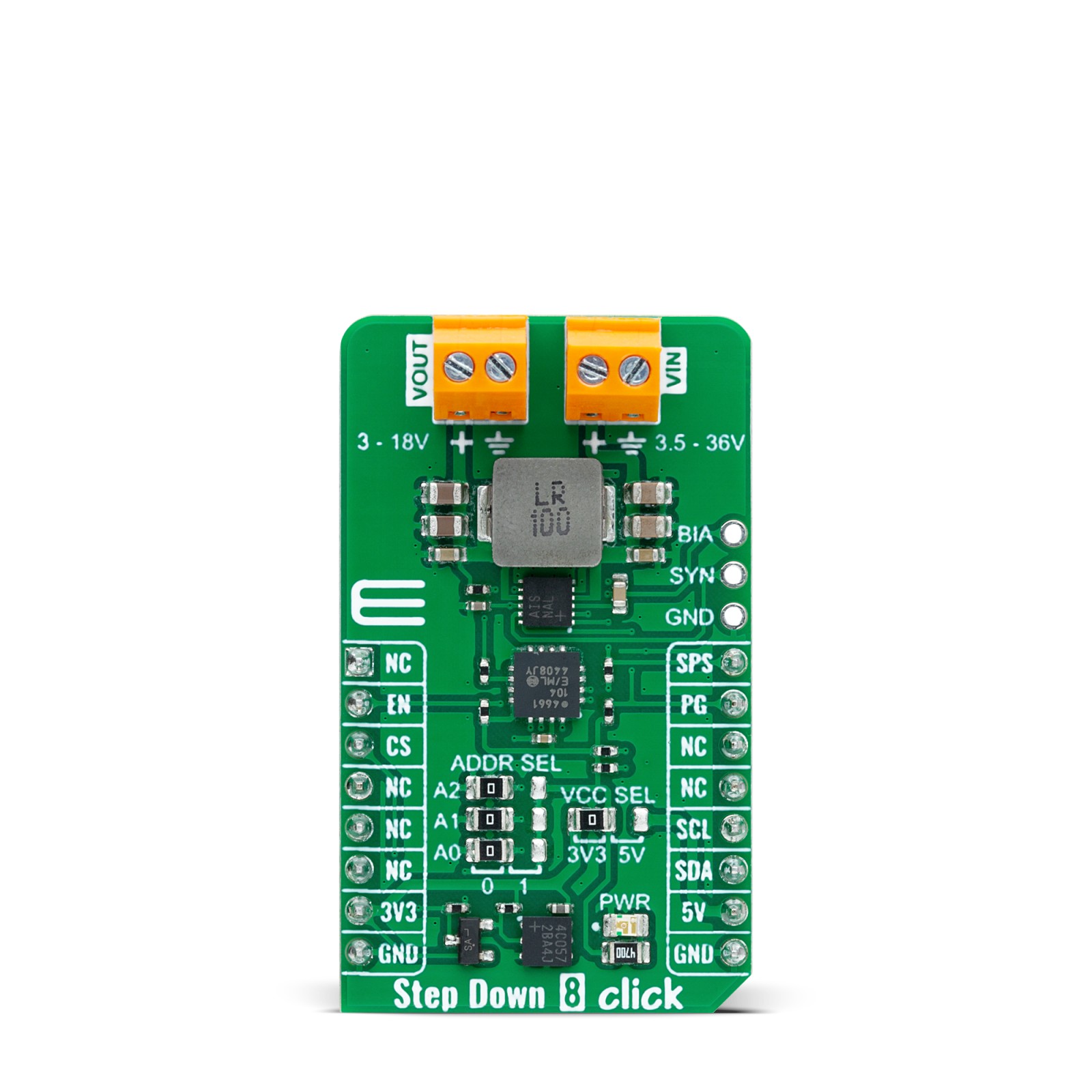
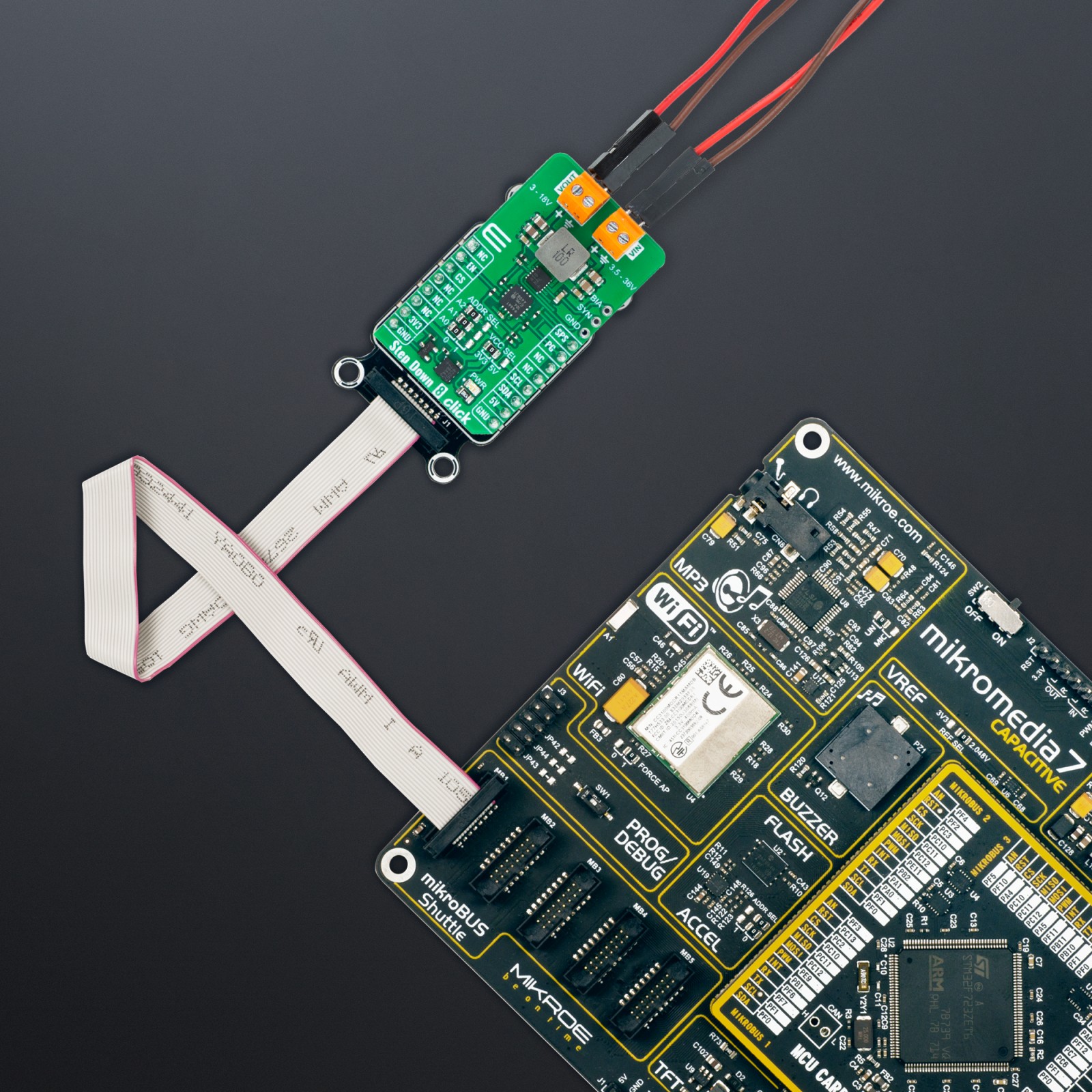
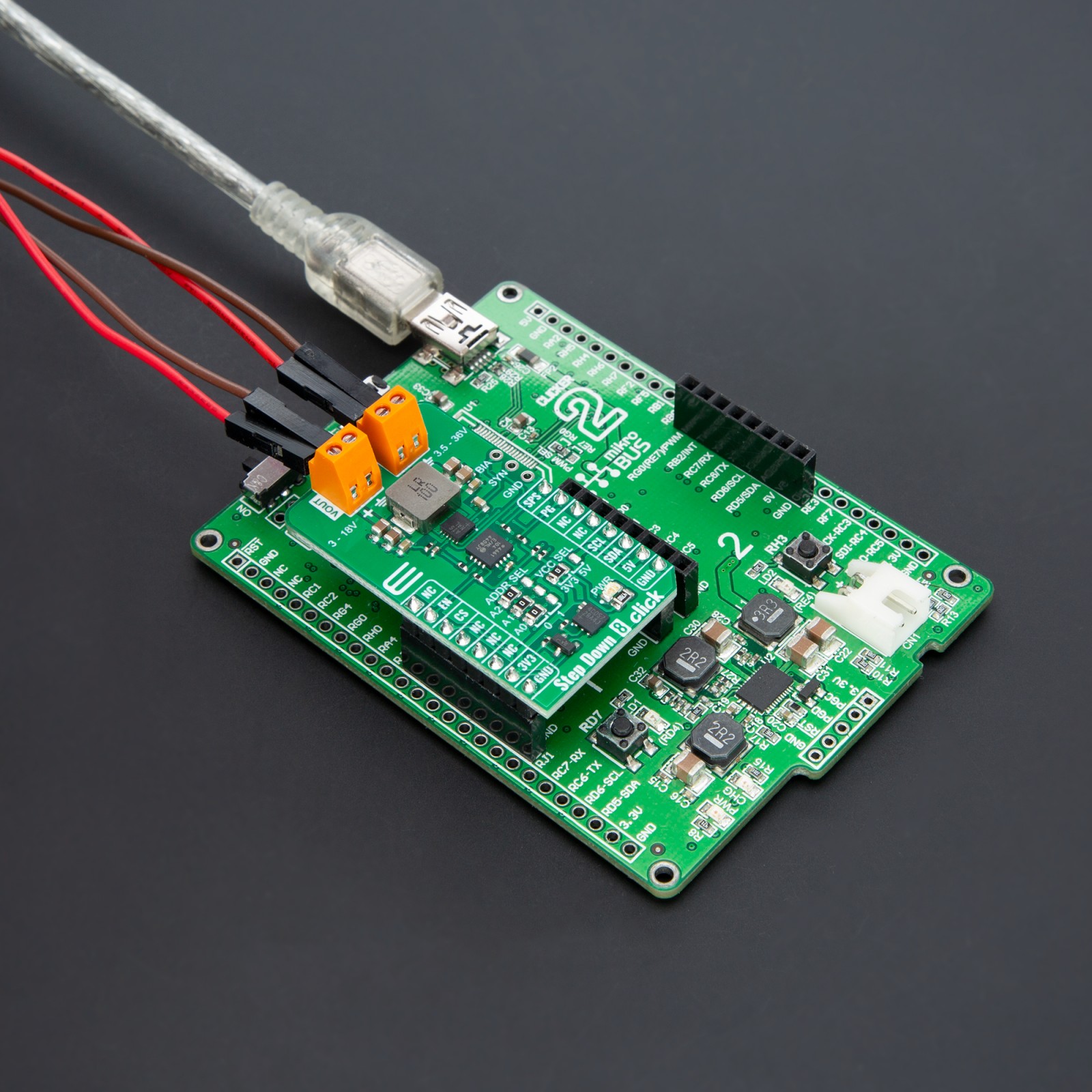
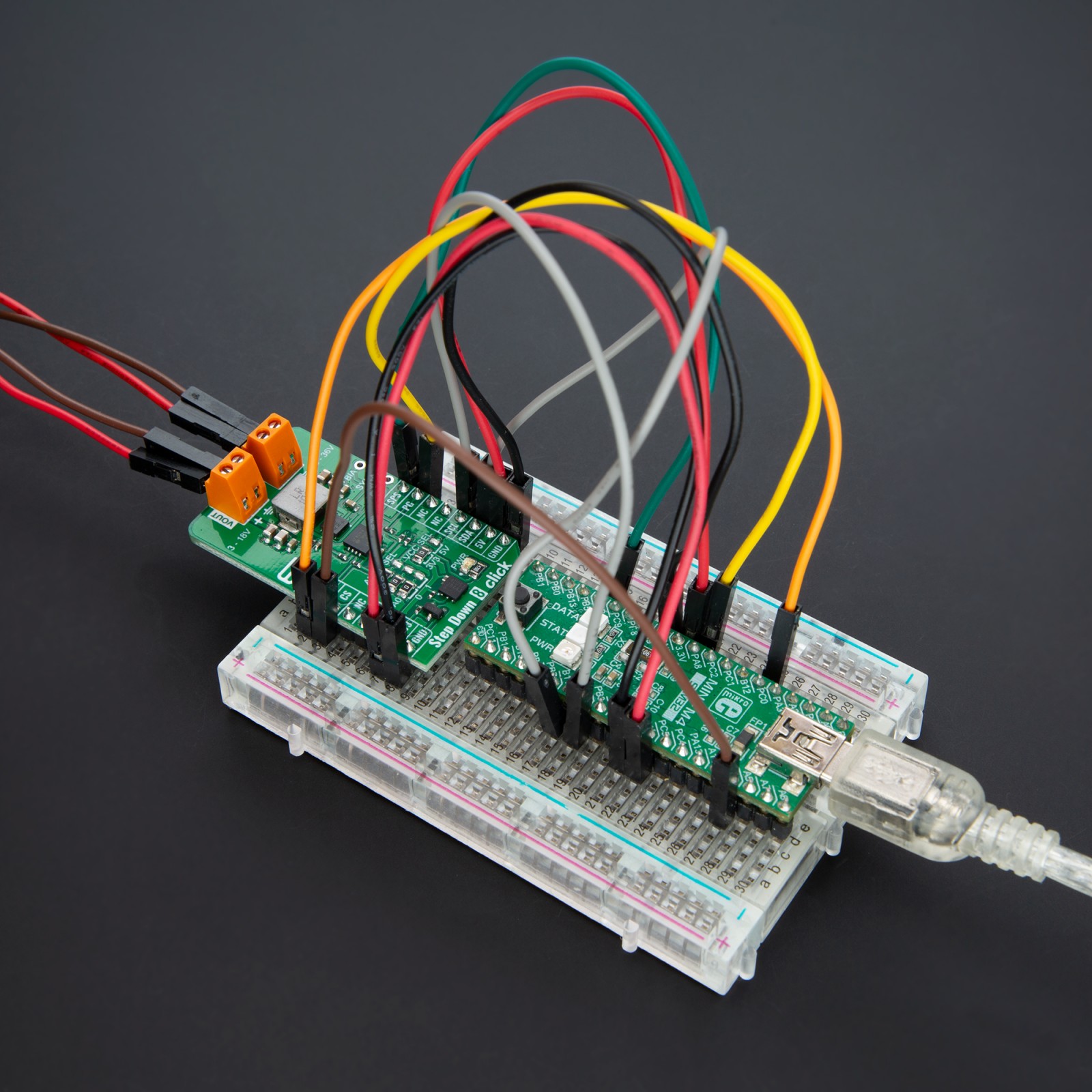
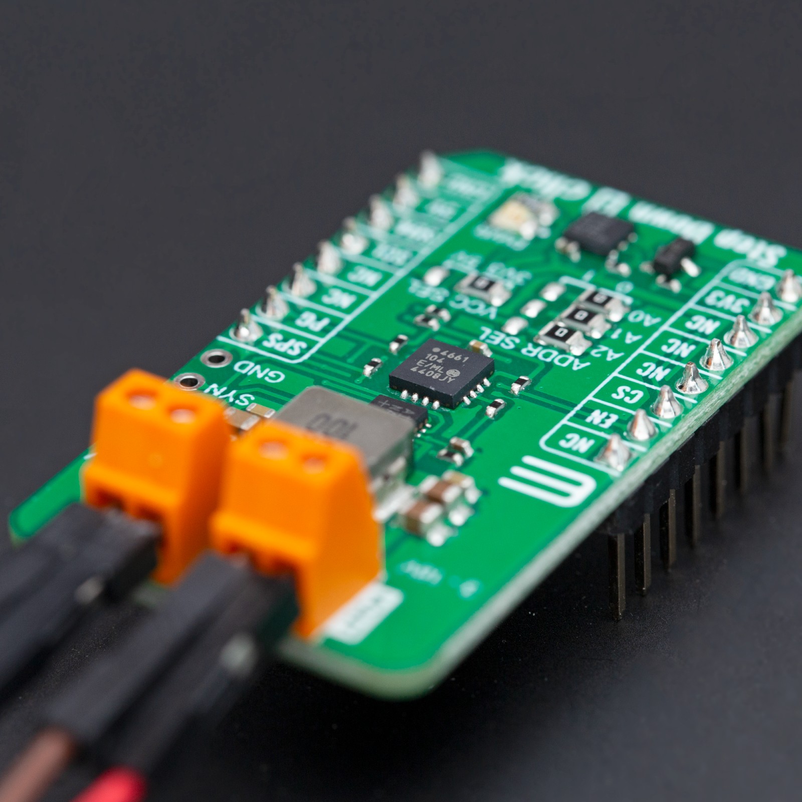
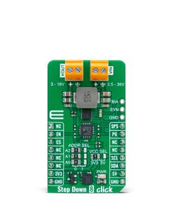
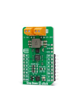
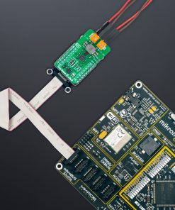
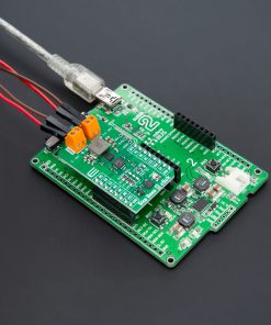
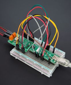
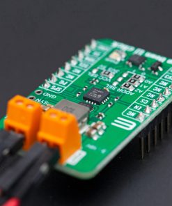
Step Down 8 Click is based on the MAX25232, a mini buck converter from Analog Devices. The MAX25232 features an under-voltage lockout, a soft-start timer, an on-chip oscillator, skip-mode operation, output-voltage overshoot protection, thermal-overload protection, and many more features. This current-mode-controlled buck converter operates at a 2.1MHz frequency, which guarantees no AM band interference, while it can also operate at 400KHz for minimum switching losses and maximum efficiency. While maintaining a 3A output current, it can stay in dropout by running at a 99% duty cycle. Voltage quality can be monitored by the host MCU.
To set the output voltage, this Click board™ uses the MCP4661, an 8-bit I2C digital potentiometer with non-volatile memory. It comes with 256 resistors and 257 wiper positions, while the last position is stored in an EEPROM. By setting the wiper value of resistance, you can set the output voltage of the MAX25232 converter available on the VOUT terminal. The Step Down 8 Click also features an unpopulated 3-pin header that allows you to set an operation mode. If you connect the SYNC pin to a GND or leave it unconnected, the device operates in a highly efficient pulse-skipping mode. If you connect SYNC to a BIAS pin or apply a clock to it, the device is in a forced-PWM mode (FPWM). Switching of modes can be done during the operation.
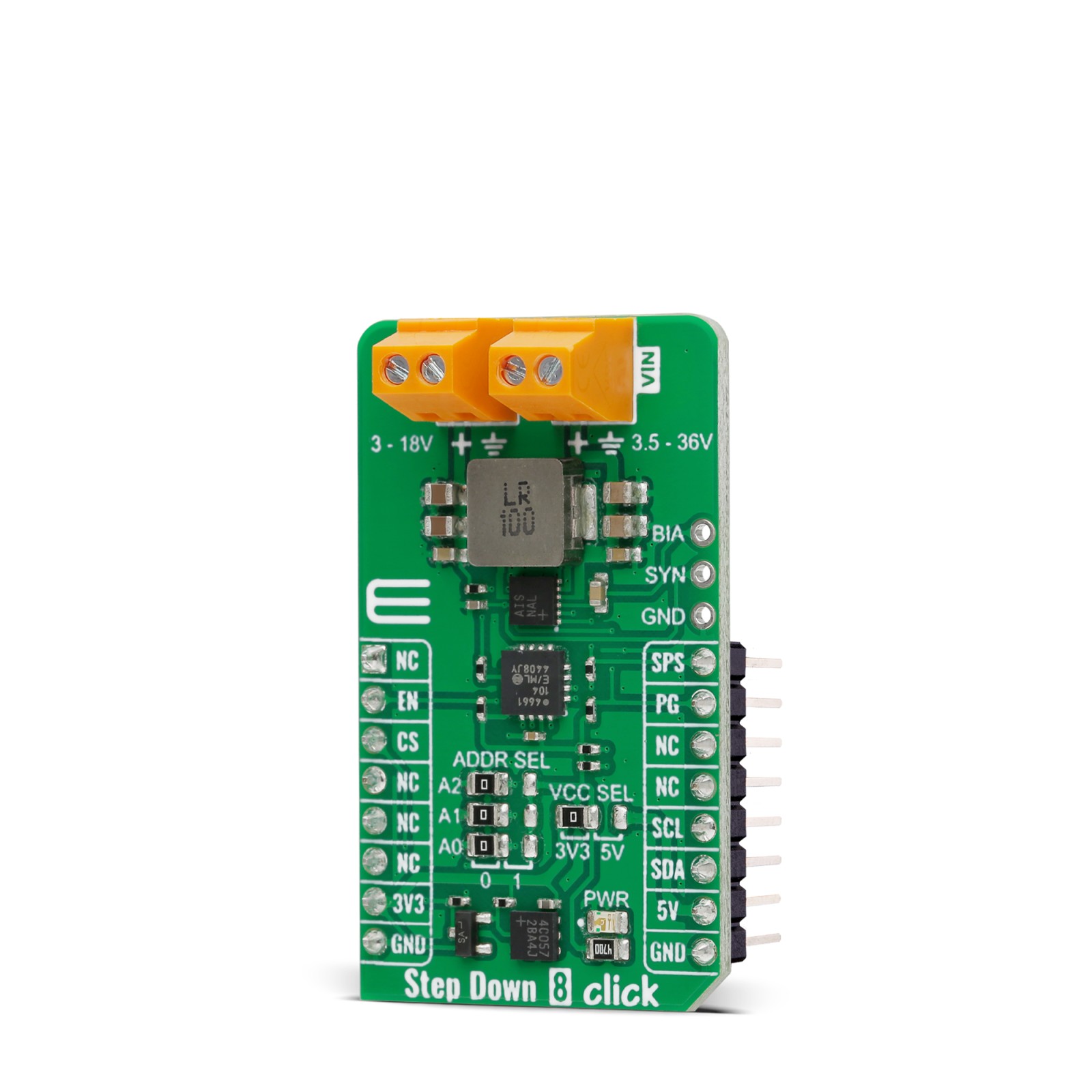
Step Down 8 Click uses a standard 2-Wire I2C interface of the MCP4661 to communicate with the host MCU, supporting 100KHz, 400KHz, and 3.4MHz frequencies. The I2C address can be set over the ADDR SEL jumpers, where the 0 position is selected by default. There is an EN enable pin to enable the converter and a PG power good pin that allows you to monitor the voltage quality. The Spread-Spectrum feature is an option that can be enabled over the SPS pin, offered to improve the EMI performance of the device. It does not interfere with the external clock applied to the SYNC pin.
This Click board™ can operate with either 3.3V or 5V logic voltage levels selected via the VCC SEL jumper. This way, both 3.3V and 5V capable MCUs can use the communication lines properly. Also, this Click board™ comes equipped with a library containing easy-to-use functions and an example code that can be used as a reference for further development.
Specifications
Type
Buck
Applications
Can be used for developing automotive, industrial applications, high-voltage DC-DC converters, and many more
On-board modules
MAX25232 – mini buck converter from Analog Devices
Key Features
Undervoltage lockout, soft-start, on-chip oscillator, skip-mode operation, highly efficient pulse-skipping mode, output voltage overshoot protection, forced-PWM mode, over-current protection, spread-spectrum option, wide voltage input, and output operating range, 3A output current, an onboard 8-bit digital potentiometer, and more
Interface
I2C
Feature
ClickID
Compatibility
mikroBUS™
Click board size
M (42.9 x 25.4 mm)
Input Voltage
3.3V or 5V
Pinout diagram
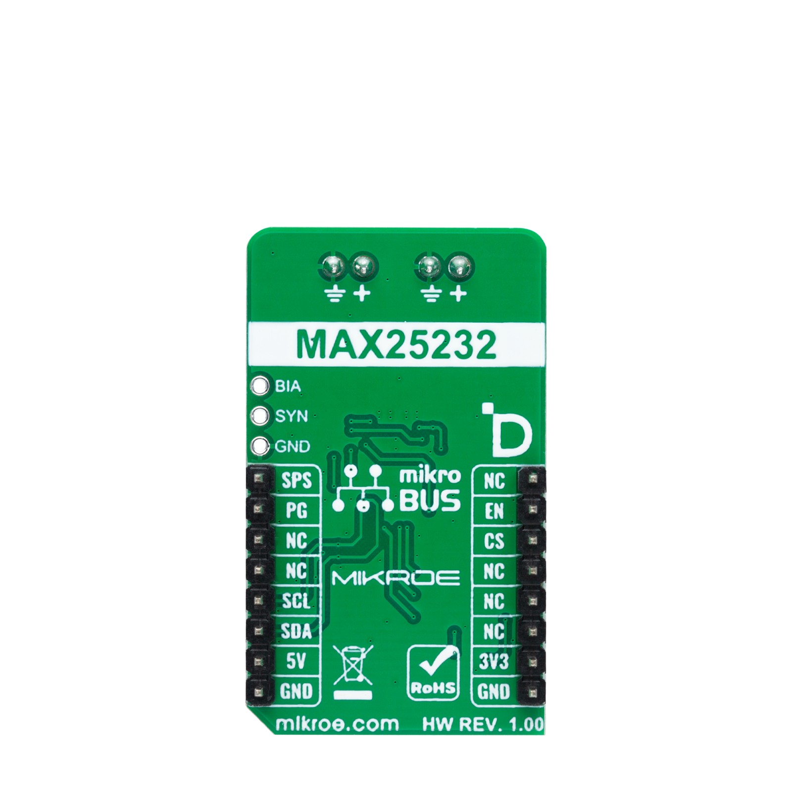
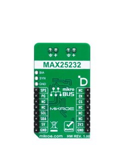
This table shows how the pinout on Step Down 8 Click corresponds to the pinout on the mikroBUS™ socket (the latter shown in the two middle columns).
Onboard settings and indicators
Label | Name | Default | Description |
---|---|---|---|
LD1 | PWR | – | Power LED Indicator |
JP1 | VCC SEL | Left | Logic Voltage Level Selection 3V3/5V: Left position 3V3, Right position 5V |
JP2-JP4 | ADDR SEL | Left | I2C Address Selection 0/1: Left position 0, Right position 1 |
Step Down 8 Click electrical specifications
Description | Min | Typ | Max | Unit |
---|---|---|---|---|
Supply Voltage | 3.3 | – | 5 | V |
Input Voltage Range | 3.5 | – | 36 | V |
Output Voltage Range | 3 | – | 18 | V |
Output Current | – | – | 3 | A |
Software Support
We provide a library for the Step Down 8 Click as well as a demo application (example), developed using MIKROE compilers. The demo can run on all the main MIKROE development boards.
Package can be downloaded/installed directly from NECTO Studio Package Manager (recommended), downloaded from our LibStock™ or found on Mikroe github account.
Library Description
This library contains API for Step Down 8 Click driver.
Key functions
-
stepdown8_set_en_pin
Step Down 8 set EN pin state function. -
stepdown8_set_wiper_pos
Step Down 8 set wiper position. -
stepdown8_set_output
Step Down 8 set output voltage.
Example Description
This library contains API for the Step Down 8 Click driver. This driver provides the functions to set the output voltage treshold.
void application_task ( void )
{
for ( uint8_t n_cnt = STEPDOWN8_MIN_OUTPUT; n_cnt <= STEPDOWN8_MAX_OUTPUT; n_cnt++ )
{
stepdown8_set_output( &stepdown8, ( float ) n_cnt );
log_printf( &logger, " Output voltage %d Vrn", ( uint16_t ) n_cnt );
Delay_ms( 2000 );
}
}
The full application code, and ready to use projects can be installed directly from NECTO Studio Package Manager (recommended), downloaded from our LibStock™ or found on Mikroe github account.
Other Mikroe Libraries used in the example:
- MikroSDK.Board
- MikroSDK.Log
- Click.StepDown8
Additional notes and informations
Depending on the development board you are using, you may need USB UART click, USB UART 2 Click or RS232 Click to connect to your PC, for development systems with no UART to USB interface available on the board. UART terminal is available in all MIKROE compilers.
mikroSDK
This Click board™ is supported with mikroSDK – MIKROE Software Development Kit. To ensure proper operation of mikroSDK compliant Click board™ demo applications, mikroSDK should be downloaded from the LibStock and installed for the compiler you are using.
For more information about mikroSDK, visit the official page.