How does it work?
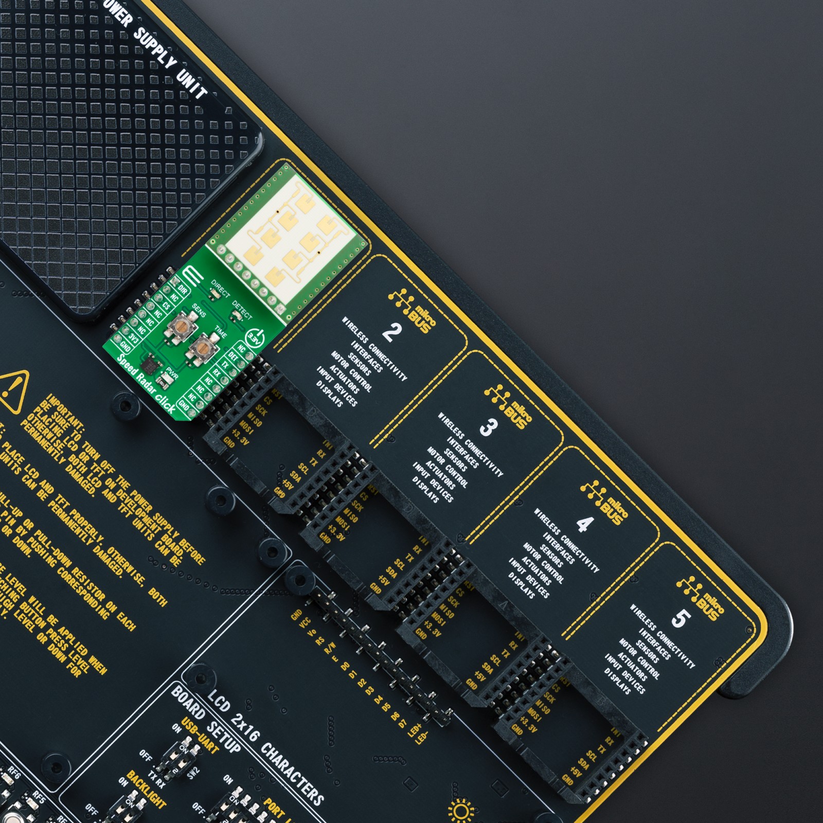
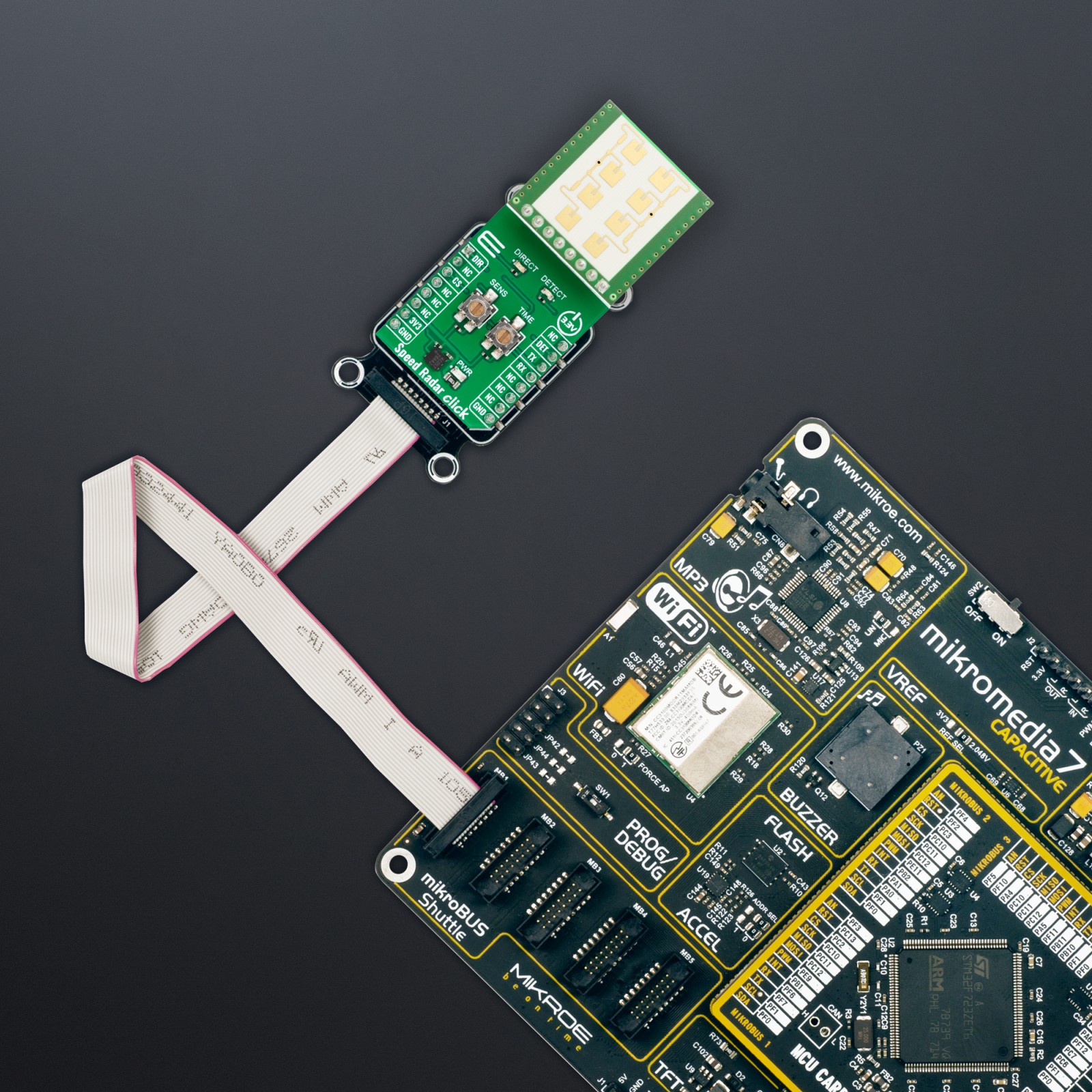
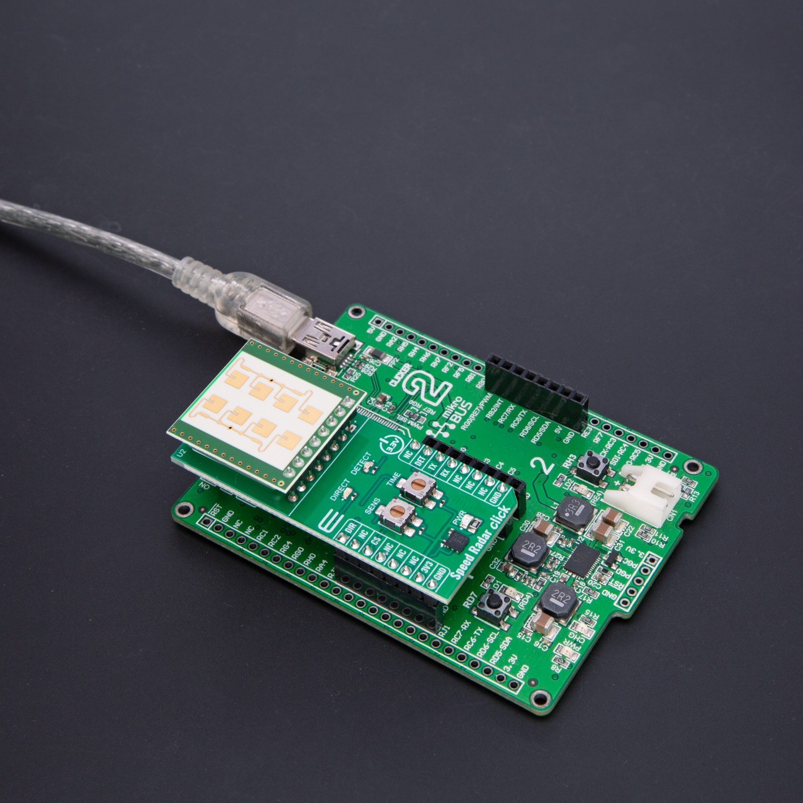
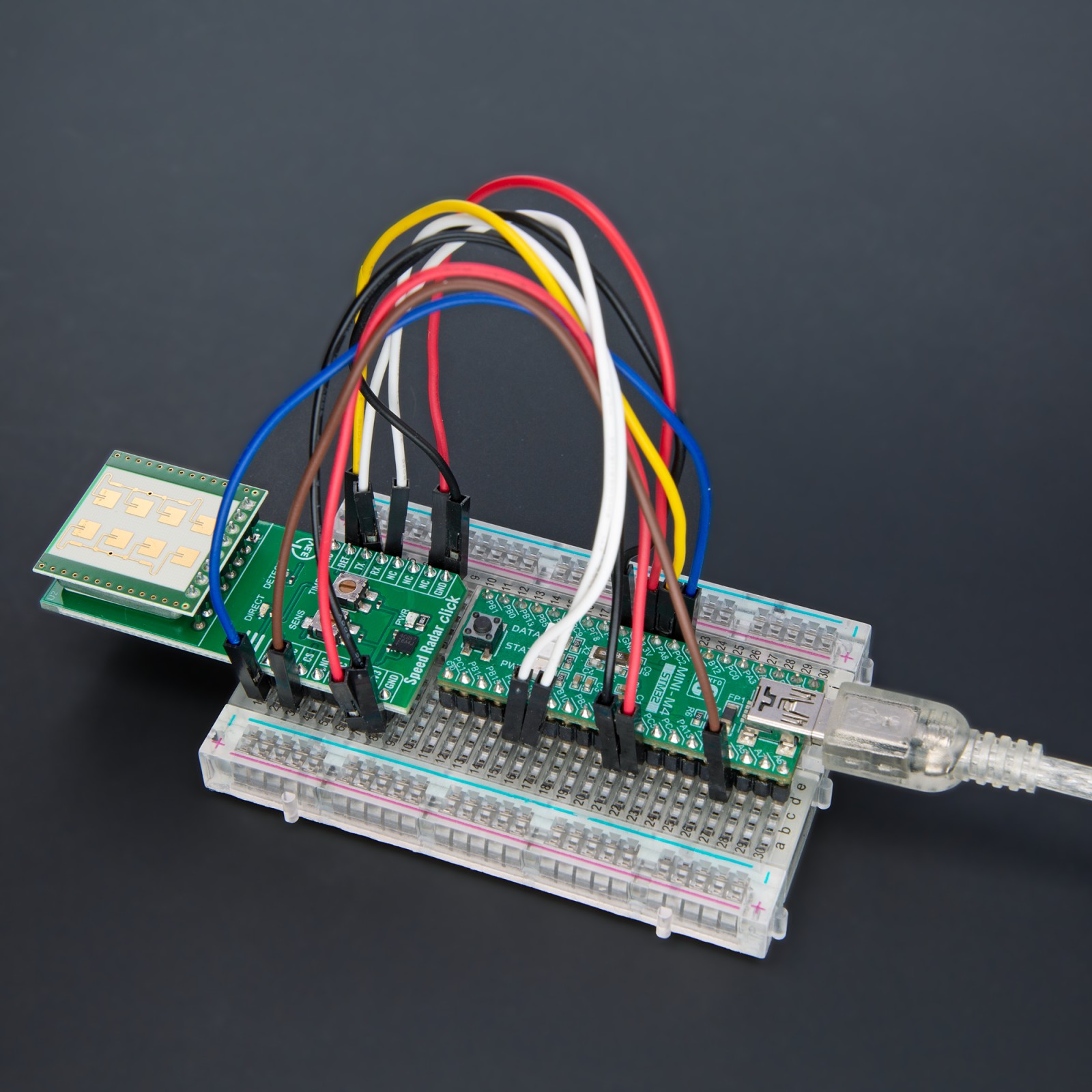
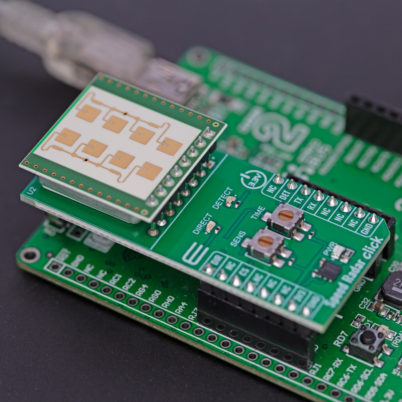
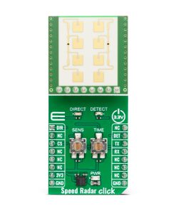
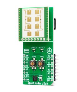
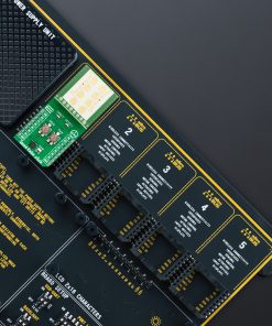
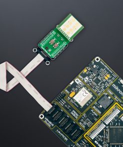
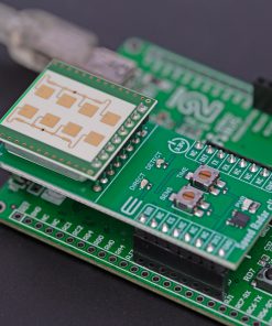
Speed Radar Click is based on the K-LD2, a radar transceiver from RFbeam. The sensor includes a 2×4 patch radar front-end antenna with an asymmetrical 80°/34° beam aperture and a powerful signal processing unit with two digital outputs for signal detection information. The sensitivity and the hold time are adjustable using analog inputs with 10K potentiometers labeled SENS and TIME. The serial interface features a powerful command set to read out advanced detection data or fully customize the detection algorithm.
Its internal I/Q Doppler signal is processed by using a complex fast Fourier transform (FFT) measurement method, which is important in the science of audio and acoustic measurements. This measurement method features easy detection of the direction of a movement, increased detection range with better SNR, efficient interference suppression, and vibration suppression. The signal processing unit samples the analog I/Q Doppler signals of the antenna and calculates a complex FFT in real-time, after which the noise and interference suppression is done. The detection algorithm looks for valid detection and digital outputs for the length of the hold time setting. I/Q Doppler signals are phase-shifted by +90° or -90° depending on the direction of a movement in the front of the sensor.
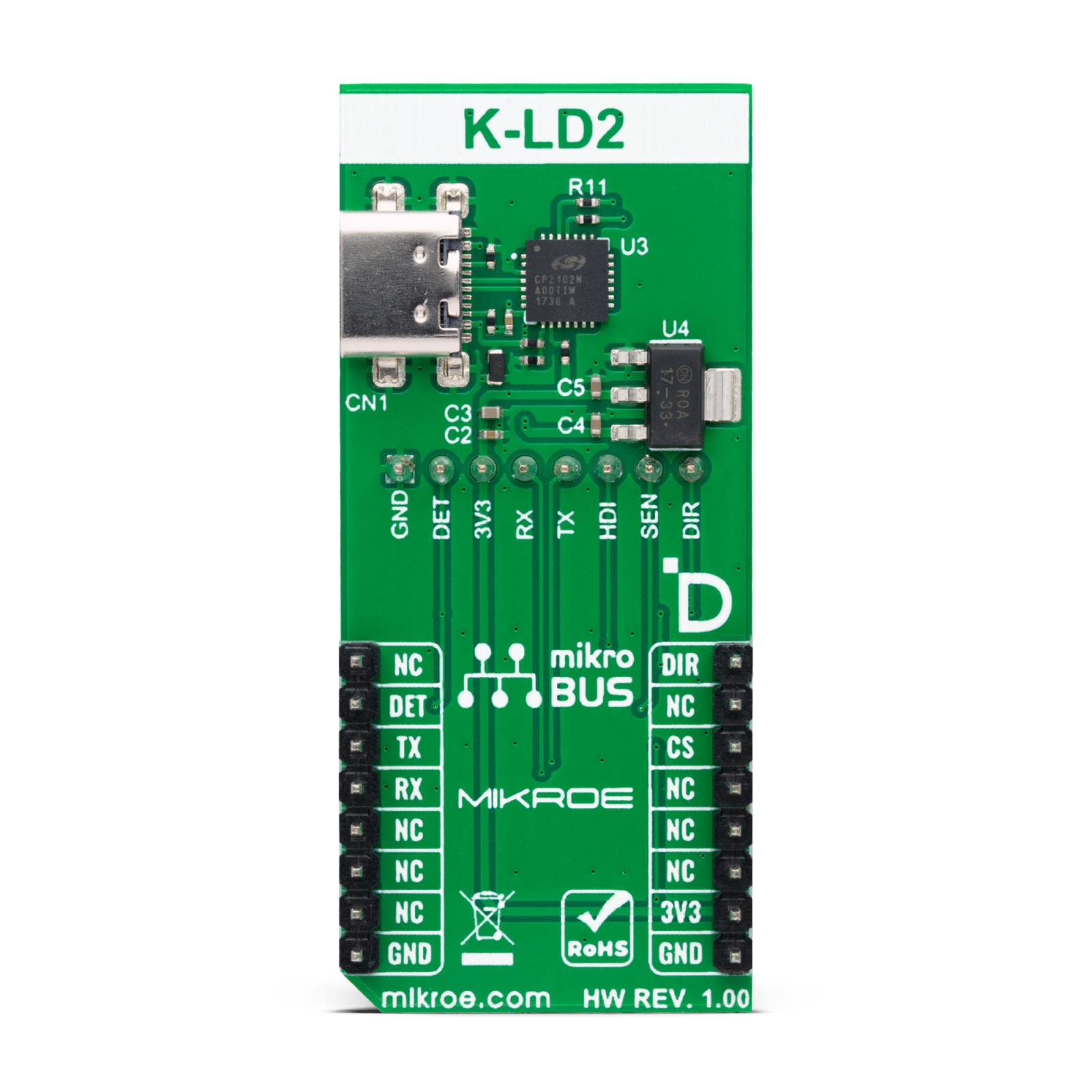
The Speed Radar Click can work as a standalone or host-driven device. It can detect the speed of any moving object, can filter out slow and fast speeds, and even detect micro speeds (very low speeds). If developing a standalone device, you can set the sensitivity and the hold time by the potentiometers. The sensitivity can be achieved in a range of 0 up to 34dB, approximately 2 to 20 meters for a walking human. The hold time can be set at 0.2 up to 160s. The sensor will filter the interferences and look for a movement with a magnitude higher than the threshold set by the sensitivity. The K-LD2 will output its detection state over the DET pin and the direction over the DIR pin of the mikroBUS™ socket along the appropriate DETECT and DIRECT LEDs. In addition, Speed Radar Click is equipped with the CP2102N, a USB-to-UART bridge from Silicon Labs, and a USB C connector for connecting this Click board™ to a PC.
Speed Radar uses a standard UART interface to communicate with the host MCU with commonly used UART RX and TX pins, supporting a baud rate of 38400bps. It will output a High logic state over the DET pin if there is a detection, and a Low if there is not. The direction output will be over the DIR pin with a Low logic state for backward/receding movement and a High logic state for forward/approaching movement. This pin is a digital miscellaneous output and can be configured for many purposes, such as detection, direction, range, and micro-detection.
This Click board™ can be operated only with a 3.3V logic voltage level. The board must perform appropriate logic voltage level conversion before using MCUs with different logic levels. Also, it comes equipped with a library containing functions and an example code that can be used as a reference for further development.
K-LD2 Radar Speed Detector GUI
The K-LD2 radar speed detector stands out for its intuitive Graphical User Interface (GUI) that simplifies parameter settings. Thanks to the onboard USB Type-C connector, users can effortlessly adjust K-LD2 parameters through the GUI. Its powerful Control Panel software sets the K-LD2 apart, dramatically reducing development time. This software allows users to modify all parameters without consulting a command list, making configuration a breeze.
For more information, software download, and in-depth GUI details, please visit RFbeam’s product page.
Specifications
Type
Motion
Applications
Can be used for the development of general movement applications, door openers, illumination of advertising boards, touch-free switches, security systems, and more
On-board modules
K-LD2 – radar transceiver from RFbeam
Key Features
24GHz radar motion detector detects humans, and cars, detects movement, and even micro movement, detects direction, stand-alone or host-driven device, patch antenna, adjustable sensitivity and hold time, USB-to-UART bridge, and USB C connector for connecting to a PC, and more
Interface
UART,USB
Feature
ClickID
Compatibility
mikroBUS™
Click board size
L (57.15 x 25.4 mm)
Input Voltage
3.3V
Pinout diagram
This table shows how the pinout on Speed Radar Click corresponds to the pinout on the mikroBUS™ socket (the latter shown in the two middle columns).
Onboard settings and indicators
Label | Name | Default | Description |
---|---|---|---|
LD1 | PWR | – | Power LED Indicator |
– | DIRECT | – | Movement Direction LED Indicator |
– | DETECT | – | Movement Detection LED Indicator |
VR1 | SENS | – | Sensitivity Adjustment Potentiometer |
VR2 | TIME | – | Hold Time Adjustment Potentiometer |
Speed Radar Click electrical specifications
Description | Min | Typ | Max | Unit |
---|---|---|---|---|
Supply Voltage | – | 3.3 | – | V |
Operating Frequency Range | 24.050 | – | 24.250 | GHz |
Software Support
We provide a library for the Speed Radar Click as well as a demo application (example), developed using MIKROE compilers. The demo can run on all the main MIKROE development boards.
Package can be downloaded/installed directly from NECTO Studio Package Manager (recommended), downloaded from our LibStock™ or found on Mikroe github account.
Library Description
This library contains API for Speed Radar Click driver.
Key functions
-
speedradar_send_command
Speed Radar send command function. -
speedradar_get_direction
Speed Radar get direction function. -
speedradar_get_detection
Speed Radar get detection function.
Example Description
This example demonstrates the use of Speed Radar Click board™ by processing the incoming data and displaying them on the USB UART.
void application_task ( void )
{
speedradar_send_command( &speedradar, SPEEDRADAR_CMD_GET_TARGET_STR );
Delay_ms( 50 );
speedradar_process( &speedradar );
if ( app_buf_len >= PROCESS_C00_RSP_LEN )
{
speedradar_target_str_display( );
speedradar_clear_app_buf( );
Delay_ms( 100 );
}
}
The full application code, and ready to use projects can be installed directly from NECTO Studio Package Manager (recommended), downloaded from our LibStock™ or found on Mikroe github account.
Other Mikroe Libraries used in the example:
- MikroSDK.Board
- MikroSDK.Log
- Click.SpeedRadar
Additional notes and informations
Depending on the development board you are using, you may need USB UART click, USB UART 2 Click or RS232 Click to connect to your PC, for development systems with no UART to USB interface available on the board. UART terminal is available in all MIKROE compilers.
mikroSDK
This Click board™ is supported with mikroSDK – MIKROE Software Development Kit. To ensure proper operation of mikroSDK compliant Click board™ demo applications, mikroSDK should be downloaded from the LibStock and installed for the compiler you are using.
For more information about mikroSDK, visit the official page.