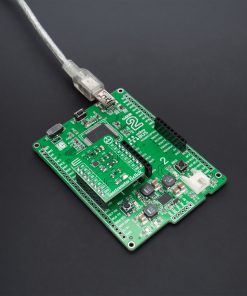
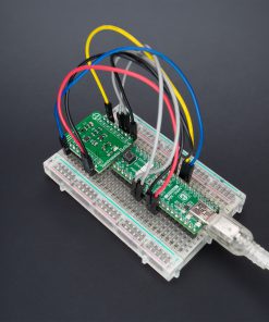
Spectrometer 2 Click
R405.00 ex. VAT
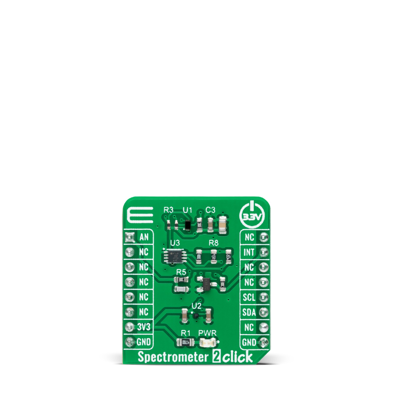
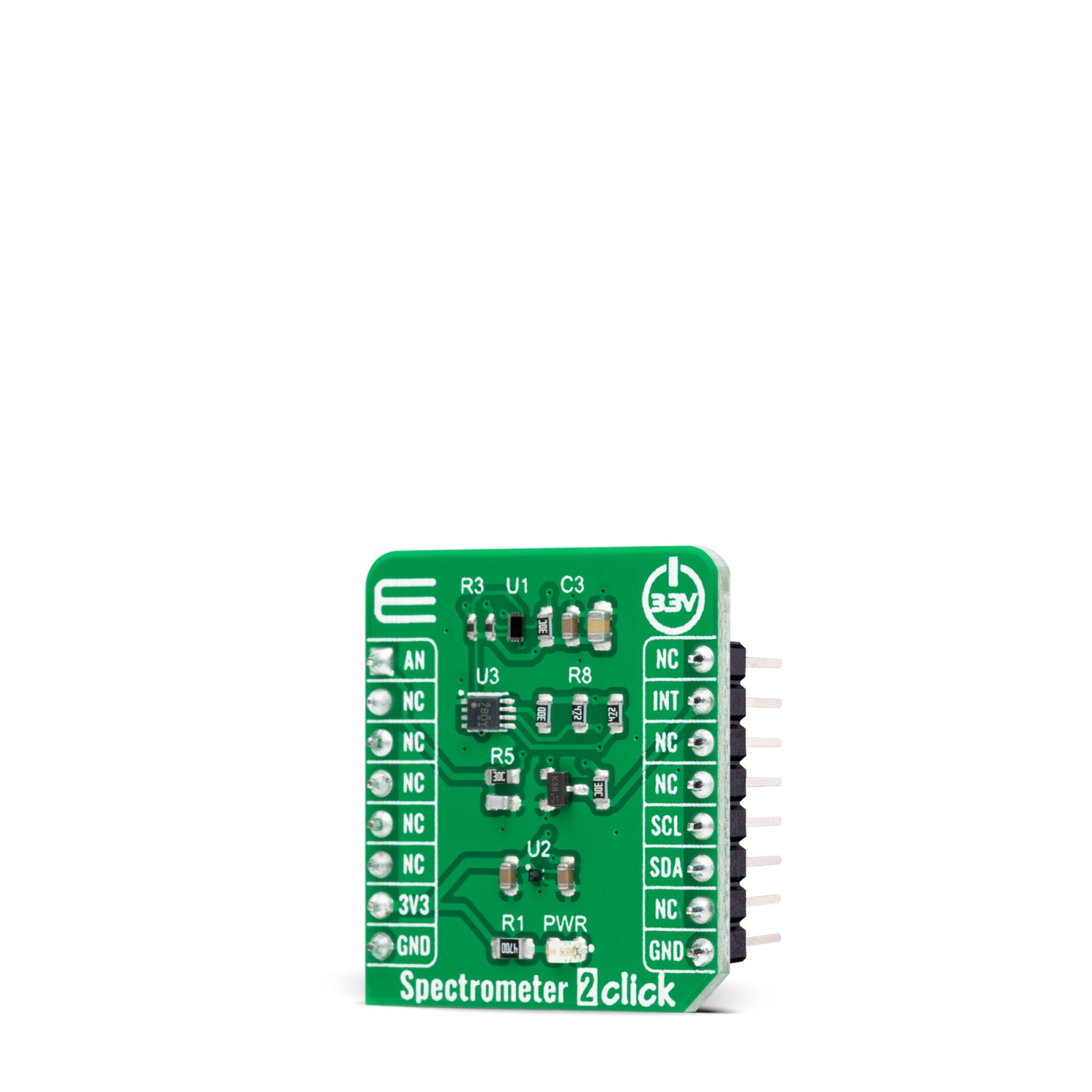
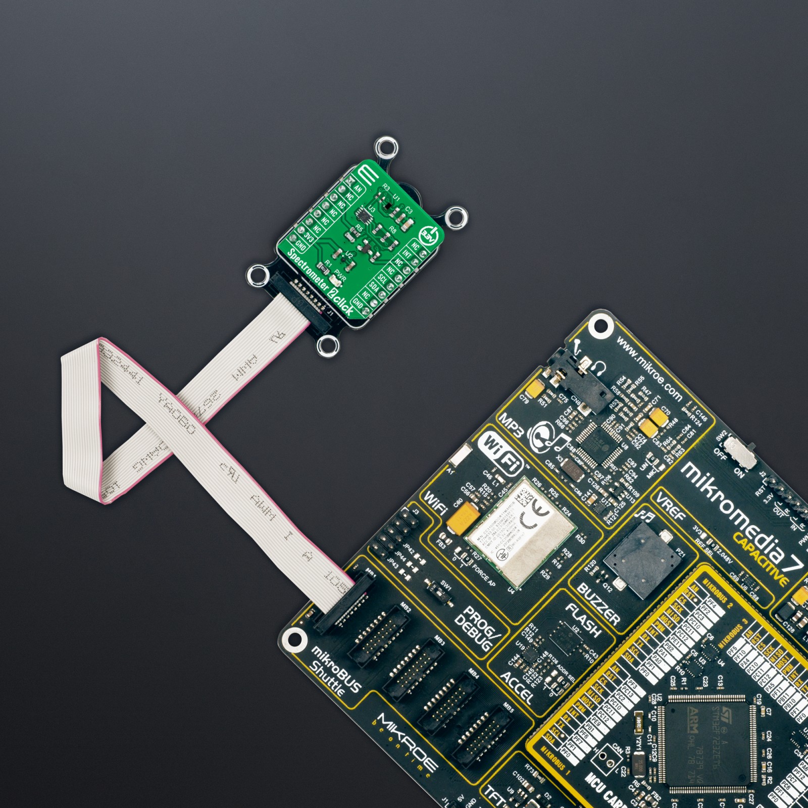
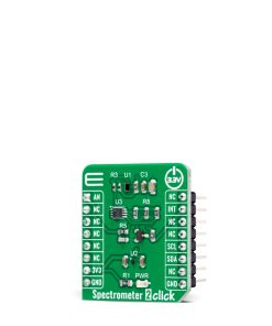
Spectrometer 2 Click is a compact add-on board that collects light waves. This board features the VD6283TX, a color sensor with advanced light flicker extraction from STMicroelectronics. The VD6283TX performs fast and accurate light measurements thanks to an individual ADC and a readout for each color channel – red, green, blue, IR, clear, and visible. It uses hybrid color filters with precise responses allowing accurate computation of the correlated color temperature (CCT) and Lux information. Its patented architecture and a high-performance photodiode design can also extract light-flickering frequencies to avoid “banding effects” or check that they are safe for the human eye. This Click board™ is suitable for screen brightness adjustment and white balance color assistance, lux and CCT measurement, or light frequency extraction for flicker correction assistance.
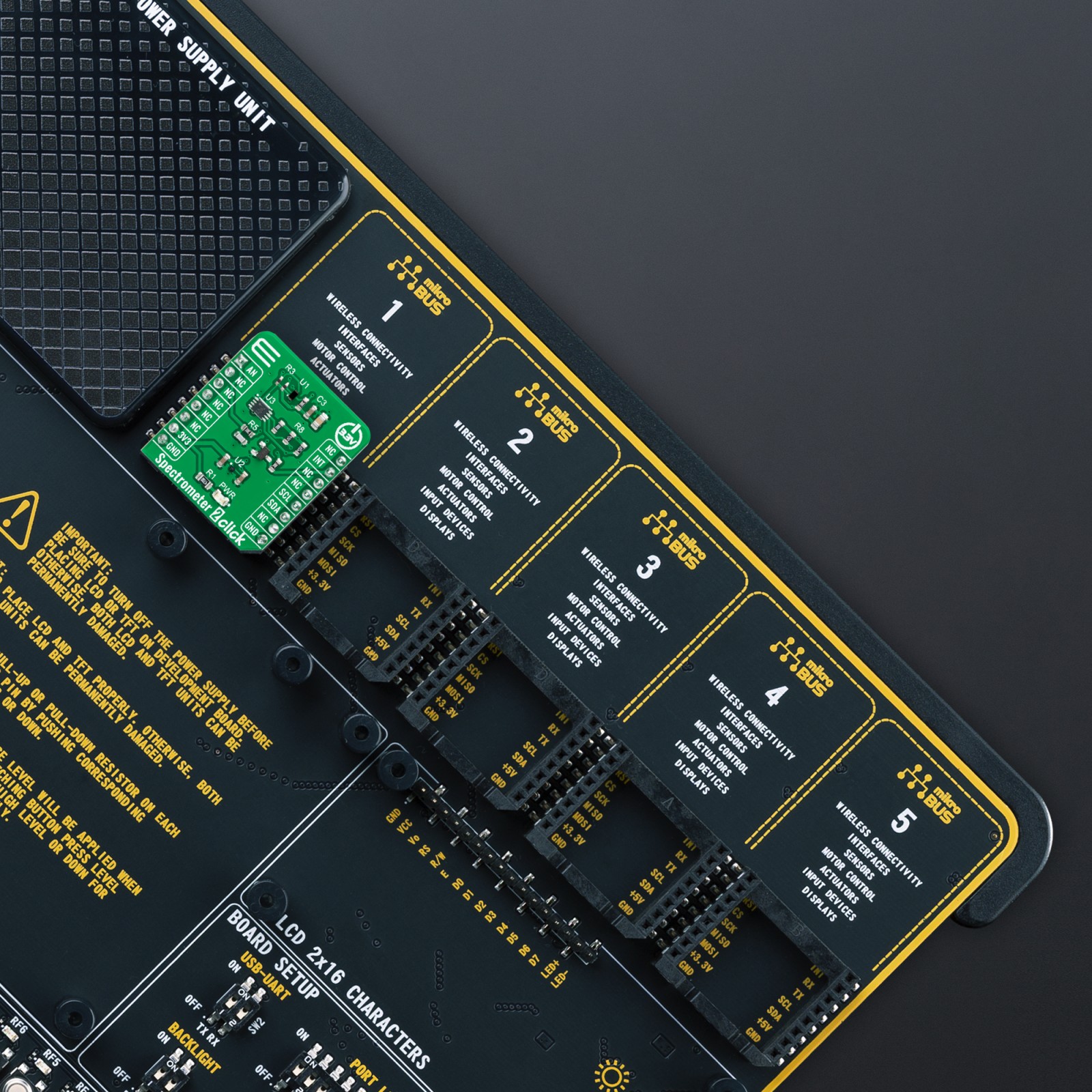
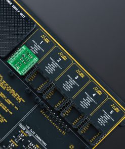
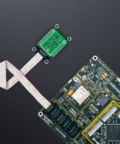
Spectrometer 2 Click is supported by a mikroSDK compliant library, which includes functions that simplify software development. This Click board™ comes as a fully tested product, ready to be used on a system equipped with the mikroBUS™ socket.
Stock: Lead-time applicable.
| 5+ | R384.75 |
| 10+ | R364.50 |
| 15+ | R344.25 |
| 20+ | R331.29 |
How does it work?
Spectrometer 2 Click as its foundation uses the VD6283TX, a color sensor with advanced light flicker extraction from STMicroelectronics. It performs fast and accurate light measurements thanks to an individual ADC with a resolution of 24 bits (16 bit + 8 bit for high accuracy under low light) and a readout for six color channels: red, green, blue, IR, clear, and visible. The color channels can be individually enabled to optimize power consumption, alongside 15 programmable gains for a high-dynamic range, through a serial interface. Six channels can operate with independent, parallel reading for ALS or flicker operations, one represents a dedicated fast channel for light flicker measurement, and one stands for an internal dark channel.

The VD6283TX uses hybrid color filters with precise responses allowing accurate computation of the correlated color temperature (CCT) and Lux information. Its patented architecture and a high-performance photodiode design can also extract light-flickering frequencies from a minimum of 100Hz and a maximum frequency of 2kHz, including LED square signals, to avoid “banding effects” or check that they are safe for the human eye.
Spectrometer 2 Click communicates with MCU using the standard I2C 2-Wire interface with a maximum clock frequency of 1MHz, fully adjustable through software registers. The VD6283TX does not require a specific Power-Up sequence but requires a voltage of 1.8V for its interface and logic part to work correctly. Therefore, a small regulating LDO is used, the ADP151, providing a 1.8V out of 3.3V mikroBUS™ power rail. Since the sensor for operation requires a power supply of 1.8V, this Click board™ also features the PCA9306 voltage-level translator allowing the VD6283TX to work with 3.3V MCU properly.
The VD6283TX can stream the following data continuously: ALS color data over the I2C interface and raw flicker data over the AN pin of the mikroBUS™ socket. It also possesses an additional interrupt signal, routed on the INT pin of the mikroBUS™ socket labeled as INT, indicating when a specific interrupt event occurs.
This Click board™ can be operated only with a 3.3V logic voltage level. The board must perform appropriate logic voltage level conversion before using MCUs with different logic levels. However, the Click board™ comes equipped with a library containing functions and an example code that can be used, as a reference, for further development.
Specifications
Type
Optical
Applications
Can be used for screen brightness adjustment and white balance color assistance, lux and CCT measurement, or light frequency extraction for flicker correction assistance
On-board modules
VD6283TX – hybrid filter multispectral sensor with light flicker engine from STMicroelectronics
Key Features
Advanced hybrid filters with high photocount response, parallel sensing of all six channels, innovative readout architecture to extract AC light flicker signal, from 100Hz to 2kHz frequency detection – sine or square wave, low power consumption, and more
Interface
Analog,I2C
Feature
No ClickID
Compatibility
mikroBUS™
Click board size
S (28.6 x 25.4 mm)
Input Voltage
3.3V
Pinout diagram
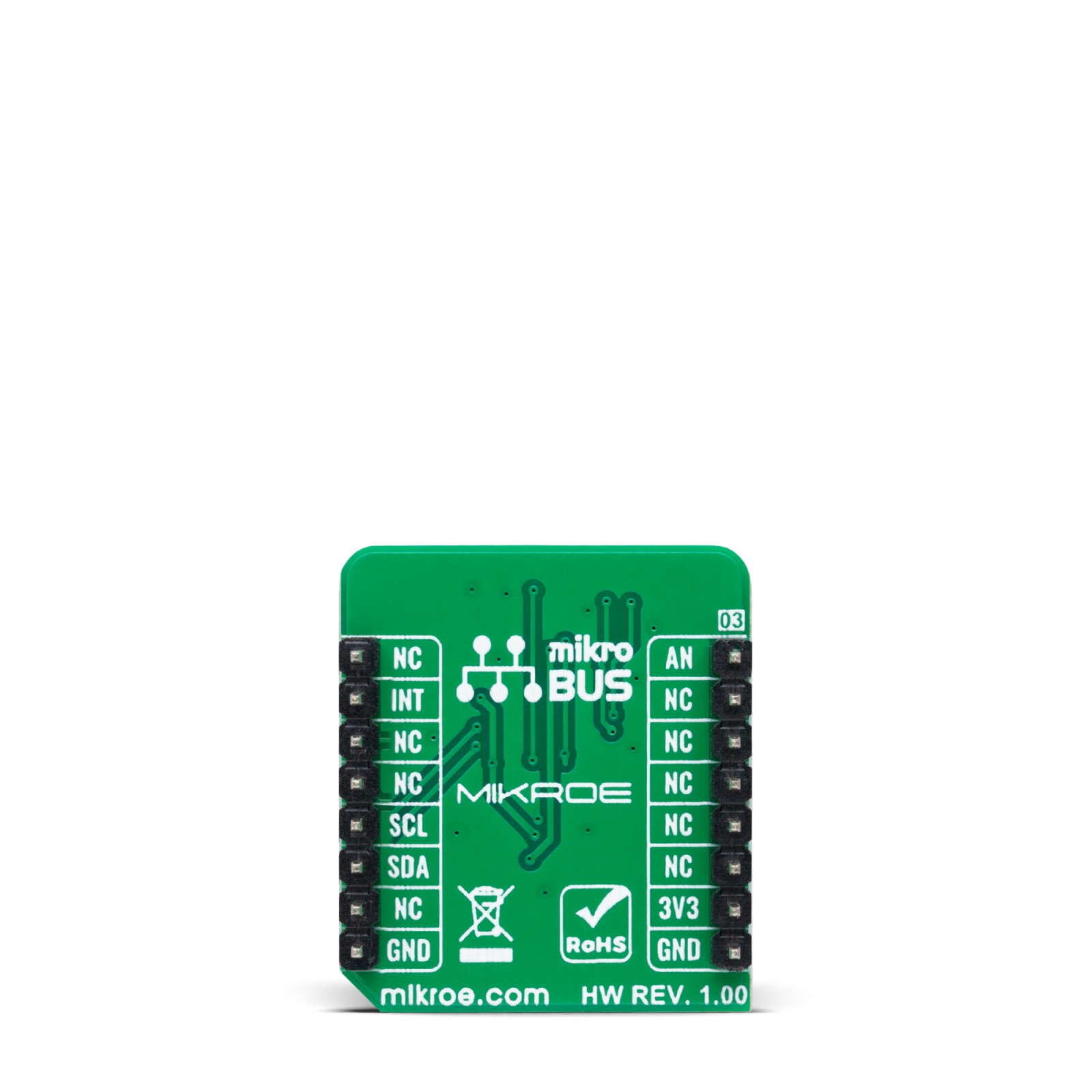
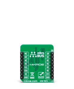
This table shows how the pinout on Spectrometer 2 Click corresponds to the pinout on the mikroBUS™ socket (the latter shown in the two middle columns).
Onboard settings and indicators
| Label | Name | Default | Description |
|---|---|---|---|
| LD1 | PWR | – | Power LED Indicator |
Spectrometer 2 Click electrical specifications
| Description | Min | Typ | Max | Unit |
|---|---|---|---|---|
| Supply Voltage | – | 3.3 | – | V |
| Peak Wavelength (R/G/B/VIS/IR/C) | 610/550/470/560/820/680 | nm | ||
| AC Flicker Frequency Detection Range | 100 | – | 2000 | Hz |
| Resolution | 16 | – | 24 | bit |
| Operating Temperature Range | -30 | +25 | +85 | °C |
Software Support
We provide a library for the Spectrometer 2 Click as well as a demo application (example), developed using MikroElektronika compilers. The demo can run on all the main MikroElektronika development boards.
Package can be downloaded/installed directly from NECTO Studio Package Manager(recommended way), downloaded from our LibStock™ or found on Mikroe github account.
Library Description
This library contains API for Spectrometer 2 Click driver.
Key functions
-
spectrometer2_get_dataThis function reads data from 6 ALS channels (Red, Visible, Blue, Green, IR, Clear). -
spectrometer2_rgbc_to_hslThis function converts RGBC (red, green, blue, clear) to HSL (hue, saturation, lightness) color value. -
spectrometer2_get_colorThis function returns the color name flag from the input HSL color.
Example Description
This example demonstrates the use of Spectrometer 2 Click board™ by reading data from 6 ALS channels and converting them to HSL color and displaying those data as well as the detected color name on the USB UART.
void application_task ( void )
 {
     // Wait for the data ready interrupt indication
     while ( !spectrometer2_get_int_pin ( &spectrometer2 ) );

     spectrometer2_als_channels_t als_channels;
     if ( ( SPECTROMETER2_OK == spectrometer2_clear_interrupt ( &spectrometer2 ) ) &&
          ( SPECTROMETER2_OK == spectrometer2_get_data ( &spectrometer2, &als_channels ) ) )
     {
         spectrometer2_hsl_t hsl;
         spectrometer2_rgbc_to_hsl( &als_channels, &hsl );
         log_printf ( &logger, "rn Hue: %.1f degrn", hsl.hue );
         log_printf ( &logger, " Saturation: %.1f %%rn", hsl.saturation );
         log_printf ( &logger, " Lightness: %.1f %%rn", hsl.lightness );
         switch ( spectrometer2_get_color ( &hsl ) )
         {
             case SPECTROMETER2_RED_COLOR:
             {
                 log_printf( &logger, " Color: REDrn" );
                 break;
             }
             case SPECTROMETER2_YELLOW_COLOR:
             {
                 log_printf( &logger, " Color: YELLOWrn" );
                 break;
             }
             case SPECTROMETER2_GREEN_COLOR:
             {
                 log_printf( &logger, " Color: GREENrn" );
                 break;
             }
             case SPECTROMETER2_CYAN_COLOR:
             {
                 log_printf( &logger, " Color: CYANrn" );
                 break;
             }
             case SPECTROMETER2_BLUE_COLOR:
             {
                 log_printf( &logger, " Color: BLUErn" );
                 break;
             }
             case SPECTROMETER2_MAGENTA_COLOR:
             {
                 log_printf( &logger, " Color: MAGENTArn" );
                 break;
             }
             case SPECTROMETER2_WHITE_COLOR:
             {
                 log_printf( &logger, " Color: WHITErn" );
                 break;
             }
             case SPECTROMETER2_BLACK_COLOR:
             {
                 log_printf( &logger, " Color: BLACKrn" );
                 break;
             }
             default:
             {
                 log_printf( &logger, " Color: UNKNOWNrn" );
                 break;
             }
         }
     }
 }
The full application code, and ready to use projects can be installed directly from NECTO Studio Package Manager(recommended way), downloaded from our LibStock™ or found on Mikroe github account.
Other Mikroe Libraries used in the example:
- MikroSDK.Board
- MikroSDK.Log
- Click.Spectrometer2
Additional notes and informations
Depending on the development board you are using, you may need USB UART click, USB UART 2 Click or RS232 Click to connect to your PC, for development systems with no UART to USB interface available on the board. UART terminal is available in all MikroElektronika compilers.
mikroSDK
This Click board™ is supported with mikroSDK – MikroElektronika Software Development Kit. To ensure proper operation of mikroSDK compliant Click board™ demo applications, mikroSDK should be downloaded from the LibStock and installed for the compiler you are using.
For more information about mikroSDK, visit the official page.
Resources
Downloads
| Weight | 16 g |
|---|---|
| Brand | MikroElektronika |
