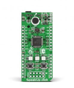


SpeakUp Click
R850.00 ex. VAT
SpeakUp Click is a compact add-on board providing an offline speech recognition solution. This board features the VS1053, an Ogg Vorbis/MP3/AAC/WMA/FLAC/MIDI audio codec from VLSI Solution. It provides an audio encoder and decoder for those formats on a single chip alongside a low-power DSP processor, data memory, 16KB instruction RAM, and 0.5KB RAM for user application. This board also contains the STM3232F415RG, an ARM Cortex-M4 32-bit MCU from STMicroelectronics. The STM32 stores many voice commands and compares them with those received from the VS1053, sends the data to the host MCU or executes the command, thus enabling this board to act as a stand-alone solution. This Click board™ makes the perfect solution for voice-controlled applications, home automation, or any human-machine interface.
Stock: Lead-time applicable.
| 5+ | R807.50 |
| 10+ | R765.00 |
| 15+ | R722.50 |
| 20+ | R695.30 |
How does it work?
SpeakUp Click is based on the VS1053, an Ogg Vorbis/MP3/AAC/WMA/FLAC/MIDI audio codec from VLSI Solution. This audio codec takes audio samples through an onboard microphone or external one connected to the 3.5mm audio jack. Received input bitstream is decoded and passed through a digital volume control to an 18-bit oversampling, multi-bit, sigma-delta DAC. The decoding is controlled via a serial control bus. In addition, it is possible to add application-specific features like DSP effects to the user RAM. On this Click board™, there is a Line Out header (L, G, R) for connecting the headphones for hearing recorded samples used for comparison.
As a brain, the SpeakUp Click features the STM32F415RG, an ARM Cortex-M4 32-bit MCU from STMicroelectronics. This MCU communicates with the VS1053 via its SPI serial interface and is responsible for processing received data from the audio codec and comparing stored voice data to the received one. It can hold more than 200 voice commands, depending on their length. Moreover, the STM32 in Standalone Mode can execute tasks according to the voice command through the HD1 and HD2 headers which contain GPIOs and 3.3V power rails. The GPIOs can have ON, OFF, Toggle, Pulse, and None states, with additional parameters for Pulse. In Click™ Mode, each recorded voice command is given an index number which can be sent to the host MCU over a USB or UART interface. In addition, the STM32 firmware can also be upgraded via the PROG JTAG header.
The SpeakUp Click, via STM32, establishes the connection with the host MCU via one of the selected mikroBUS™ interfaces (UART, SPI, or I2C). UART interface is set as default, while SPI/I2C can be an additional communication method if users want to create their own libraries. Also, the user is provided with other functions for STM32, such as reset function, interrupt, and PWM from the mikroBUS™ socket. Using onboard push buttons makes it possible to perform some basic configurations without using the software. Push button SW1 is used for recording voice commands that shouldn’t last more than 1 second while pressing SW2 push button for more than 2 seconds erases all recorded voice commands. Both pressed push buttons will reset the Click board™. There are two LEDs, amber and red, to provide the board’s visual status.
We also provide a free SpeakUp application based on the Dynamic Time Warping (DTW) algorithm that lets you configure this Click board™ through the software. SpeakUp Click board features a mini USB connector to connect the board to the PC and recognizes it as HID. After a successful connection, the SpeakUp Click board™ will perform ambient noise detection and will calibrate itself, which is a process that will last about 10 seconds. The application for the PC allows you to add voice commands to the SpeakUp Click with a predicted time limit per command. The recorded command will be automatically played so you can make sure it is ok and can be named to avoid future confusion. Application settings have the configuration for acceptance threshold, recording timeout, word length, and more.
NOTE: You can find the complete instructions for using and configuring the SpeakUp Click in our User Manual.
This Click board™ can be operated only with a 3.3V logic voltage level. The board must perform appropriate logic voltage level conversion before using MCUs with different logic levels.
Specifications
Type
Speech recognition
Applications
Can be used for voice-controlled applications, home automation, or any human-machine interface
On-board modules
VS1053 – audio codec from VLSI Solution
STM32F415RG – ARM Cortex-M4 32-bit MCU from STMicroelectronics
Key Features
Recognize over 200 different voice commands, Standalone capabilities with user programmable GPIOs, onboard MCU, sound received through internal or external mic, comes with a dedicated software tool for easy configuration, selectable serial interface, ultra fast operation, and more
Interface
I2C,PWM,SPI,UART,USB
Feature
No ClickID
Compatibility
mikroBUS™
Click board size
L (57.15 x 25.4 mm)
Input Voltage
3.3V
Pinout diagram
This table shows how the pinout on SpeakUp Click corresponds to the pinout on the mikroBUS™ socket (the latter shown in the two middle columns).
| Notes | Pin | Pin | Notes | ||||
|---|---|---|---|---|---|---|---|
| NC | 1 | AN | PWM | 16 | PWM | PWM Signal | |
| Reset | RST | 2 | RST | INT | 15 | INT | Interrupt |
| SPI Chip Select | CS | 3 | CS | RX | 14 | TX | UART TX |
| SPI Clock | SCK | 4 | SCK | TX | 13 | RX | UART RX |
| SPI Data OUT | SDO | 5 | MISO | SCL | 12 | SCL | I2C Clock |
| SPI Data IN | SDI | 6 | MOSI | SDA | 11 | SDA | I2C Data |
| Power Supply | 3.3V | 7 | 3.3V | 5V | 10 | NC | |
| Ground | GND | 8 | GND | GND | 9 | GND | Ground |
Onboard settings and indicators
| Label | Name | Default | Description |
|---|---|---|---|
| LD1 | LD1 | – | Ready for Recording and Listening Status LED Indicator |
| LD2 | LD2 | – | Operational Status LED Indicator |
| LD3 | PWR | – | Power LED Indicator |
| SW1 | SW1 | Populated | Button for Recording the Voice Command |
| SW2 | SW2 | Populated | Button for Deleting Voice Command |
| HD1-HD2 | – | Unpopulated | User-Programmable GPIOs Headers |
| HD3 | LINE OUT | Unpopulated | Stereo Headphone Header |
| CN4 | PROG | Unpopulated | JTAG Programming Header |
SpeakUp Click electrical specifications
| Description | Min | Typ | Max | Unit |
|---|---|---|---|---|
| Supply Voltage | – | 3.3 | – | V |
Resources
Downloads
| Weight | 38 g |
|---|---|
| Brand | MikroElektronika |