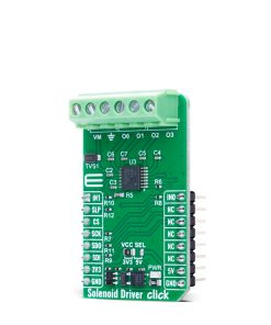
Solenoid Driver Click
R270.00 ex. VAT
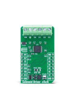
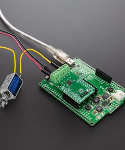
Solenoid Driver Click is a compact add-on board designed to drive inductive loads such as solenoids and valves in automotive and industrial applications. It is based on the DRV81004-Q1, a four-channel low-side switch from Texas Instruments with integrated protection and diagnostic features. It features four N-channel MOSFETs with 700mΩ ON resistance, supports up to 470mA per output when all channels are active, and operates from a wide external supply voltage range of 3V to 40V. It offers SPI communication with daisy-chain support, PWM control via input pins, and an Input Mapping function that allows flexible output control. Built-in safety features include overcurrent and overtemperature protection, as well as open-load diagnostics and energy clamp circuits for inductive load switching. This Click board™ is ideal for use in Zone Control Modules, Body Control Modules, HVAC systems, lighting control, engine systems, and industrial PLC applications.
Solenoid Driver Click is fully compatible with the mikroBUS™ socket and can be used on any host system supporting the mikroBUS™ standard. It comes with the mikroSDK open-source libraries, offering unparalleled flexibility for evaluation and customization. What sets this Click board™ apart is the groundbreaking ClickID feature, enabling your host system to automatically detect and identify this add-on board.
Stock: Lead-time applicable.
| 5+ | R256.50 |
| 10+ | R243.00 |
| 15+ | R229.50 |
| 20+ | R220.86 |
How does it work?
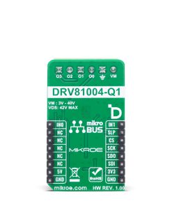
Solenoid Driver Click is based on the DRV81004-Q1, a four-channel low-side switch from Texas Instruments designed to drive inductive loads such as solenoids and valves in automotive and industrial applications. This automotive-grade IC integrates four N-channel power MOSFET low-side switches, each with a typical ON resistance of 700mΩ, and supports up to 470mA current (42VDS) per output (O0-O3) when all channels are active simultaneously. Operating from an external power supply in the range of 3V to 40V on the VM terminal, this device offers robust and flexible control for various low-voltage applications, including Zone Control Modules (ZCM), Body Control Modules (BCM), HVAC systems, automotive lighting, engine systems, Vehicle Control Units (VCUs), and industrial Programmable Logic Controllers (PLCs).
The DRV81004-Q1 supports communication and diagnostics through a 16-bit SPI interface with a maximum frequency of 5MHz, and allows for a daisy chain configuration enabling multiple devices to be connected to the same SPI bus, even in mixed 8-bit/16-bit environments. Additionally, two input pins (IN0 and IN1) allow for direct PWM control of the outputs, while the Input Mapping function provides the ability to assign different outputs to a single input signal or control multiple channels with a single pin. In Limp Home mode, input pins are routed directly to outputs O2 and O3, allowing channels to operate even when the digital supply is unavailable, providing redundancy in critical systems.
Integrated protection features include overcurrent protection, where affected channels automatically shut down upon detecting excessive current and may be reactivated via SPI, as well as overtemperature protection using dedicated sensors per channel. The device also enables Open Load diagnostics in the OFF state via an internal current source configurable over SPI, enhancing fault detection and system reliability. To handle inductive kickback, each output includes a built-in clamp circuit to safely dissipate stored energy when turning off inductive loads.
This Click board™ can operate with either 3.3V or 5V logic voltage levels selected via the VCC SEL jumper. This way, both 3.3V and 5V capable MCUs can use the communication lines properly. Also, this Click board™ comes equipped with a library containing easy-to-use functions and an example code that can be used as a reference for further development.
Specifications
Type
Relay
Applications
Ideal for use in Zone Control Modules, Body Control Modules, HVAC systems, lighting control, engine systems, and industrial PLC applications
On-board modules
DRV81004-Q1 – four-channel low-side switch from Texas Instruments
Key Features
Four low-side N-channel MOSFET outputs with 700mΩ ON resistance, support for up to 470mA current per channel when all outputs are active, wide operating voltage range, 16-bit SPI interface with 5MHz maximum clock and daisy-chain capability, PWM control, Input Mapping function, Limp Home mode operation, integrated protection features with automatic shutdown and reactivation via SPI, and more
Interface
GPIO,SPI
Feature
ClickID
Compatibility
mikroBUS™
Click board size
M (42.9 x 25.4 mm)
Input Voltage
3.3V or 5V,External
Pinout diagram
This table shows how the pinout on Solenoid Driver Click corresponds to the pinout on the mikroBUS™ socket (the latter shown in the two middle columns).
| Notes | Pin | Pin | Notes | ||||
|---|---|---|---|---|---|---|---|
| Output Control | IN1 | 1 | AN | PWM | 16 | IN0 | Output Control |
| Sleep Mode / ID SEL | SLP | 2 | RST | INT | 15 | NC | |
| SPI Select / ID COMM | CS | 3 | CS | RX | 14 | NC | |
| SPI Clock | SCK | 4 | SCK | TX | 13 | NC | |
| SPI Data OUT | SDO | 5 | MISO | SCL | 12 | NC | |
| SPI Data IN | SDI | 6 | MOSI | SDA | 11 | NC | |
| Power Supply | 3.3V | 7 | 3.3V | 5V | 10 | 5V | Power Supply |
| Ground | GND | 8 | GND | GND | 9 | GND | Ground |
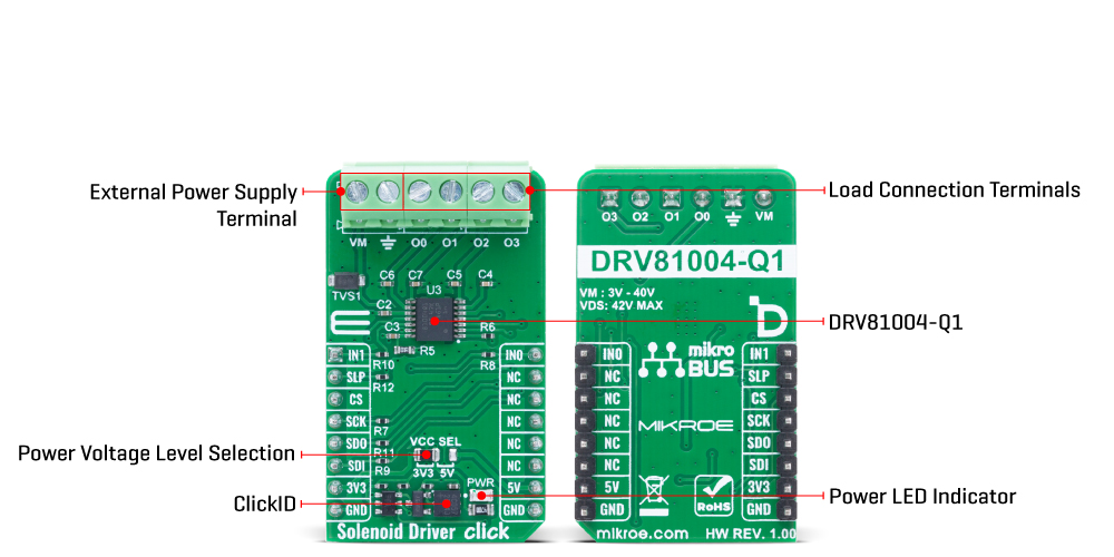
Onboard settings and indicators
| Label | Name | Default | Description |
|---|---|---|---|
| LD1 | PWR | – | Power LED Indicator |
| JP1 | VCC SEL | Left | Power Voltage Level Selection 3V3/5V: Left position 3V3, Right position 5V |
Solenoid Driver Click electrical specifications
| Description | Min | Typ | Max | Unit |
|---|---|---|---|---|
| Supply Voltage | 3.3 | – | 5 | V |
| External Power Supply | 3 | – | 40 | V |
| Output Current (all channels) | – | – | 470 | mA |
| ON Resistance (per output) | – | 0.7 | – | Ω |
Software Support
Solenoid Driver Click demo application is developed using the NECTO Studio, ensuring compatibility with mikroSDK‘s open-source libraries and tools. Designed for plug-and-play implementation and testing, the demo is fully compatible with all development, starter, and mikromedia boards featuring a mikroBUS™ socket.
Example Description
This example demonstrates the use of the Solenoid Driver Click board by enabling output channels one by one in a round-robin fashion and parsing the diagnostic status after each update. The diagnosis includes undervoltage detection, output fault status, and operation mode.
Key Functions
solenoiddriver_cfg_setupThis function initializes Click configuration structure to initial values.solenoiddriver_initThis function initializes all necessary pins and peripherals used for this Click board.solenoiddriver_default_cfgThis function executes a default configuration of Solenoid Driver Click board.solenoiddriver_set_outputThis function sets the desired output control configuration to the output control register.solenoiddriver_clear_latchThis function clears all latch output states via register write.
Application Init
Initializes the logger and the Click board driver, and applies the default configuration.
Application Task
Sequentially enables each output channel with a 1-second delay, checks the diagnostic register, logs operation status, and clears the latch register.
Application Output
This Click board can be interfaced and monitored in two ways:
- Application Output – Use the “Application Output” window in Debug mode for real-time data monitoring. Set it up properly by following this tutorial.
- UART Terminal – Monitor data via the UART Terminal using a USB to UART converter. For detailed instructions, check out this tutorial.
Additional Notes and Information
The complete application code and a ready-to-use project are available through the NECTO Studio Package Manager for direct installation in the NECTO Studio. The application code can also be found on the MIKROE GitHub account.
Resources
Downloads
| Weight | 20 g |
|---|---|
| Brand | MikroElektronika |