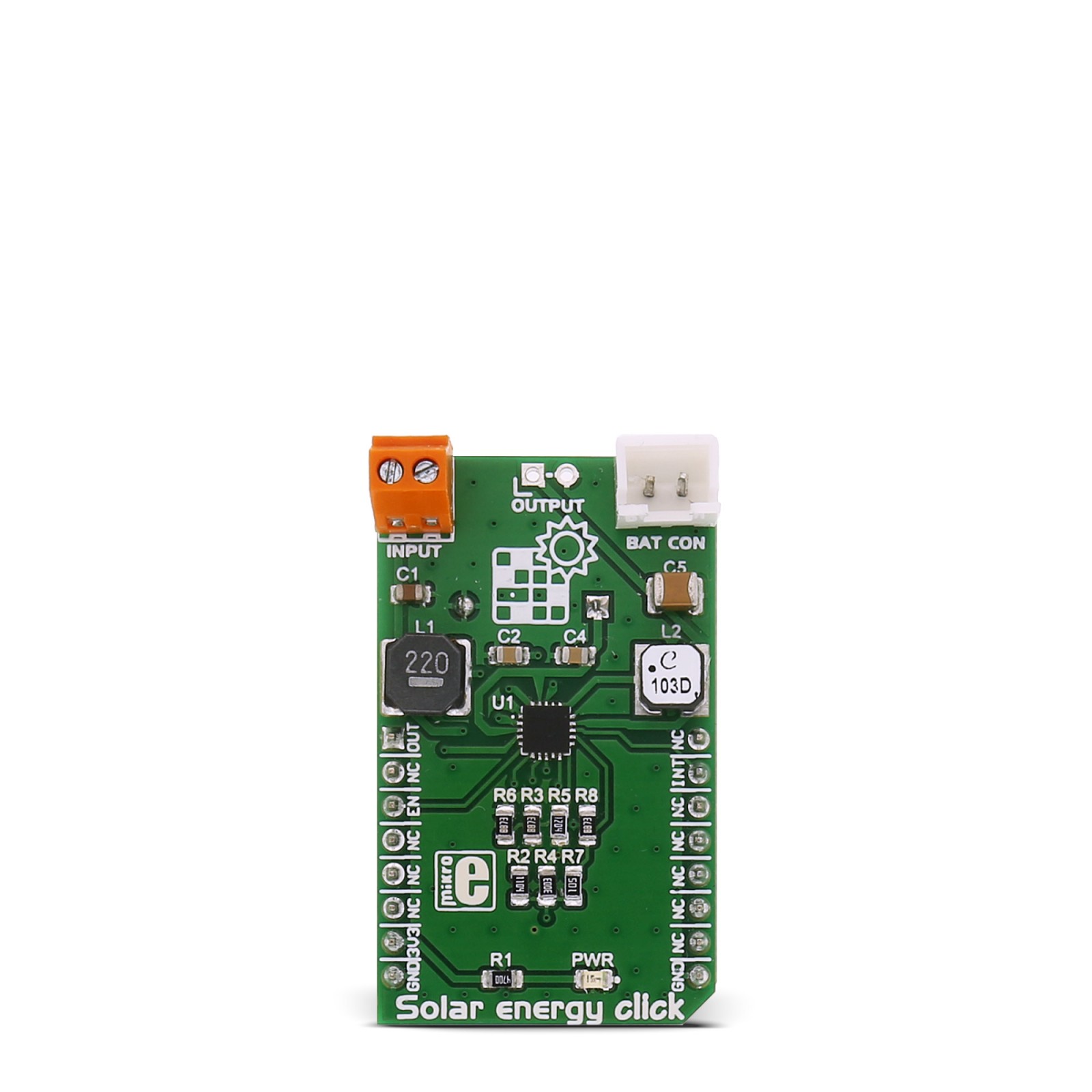
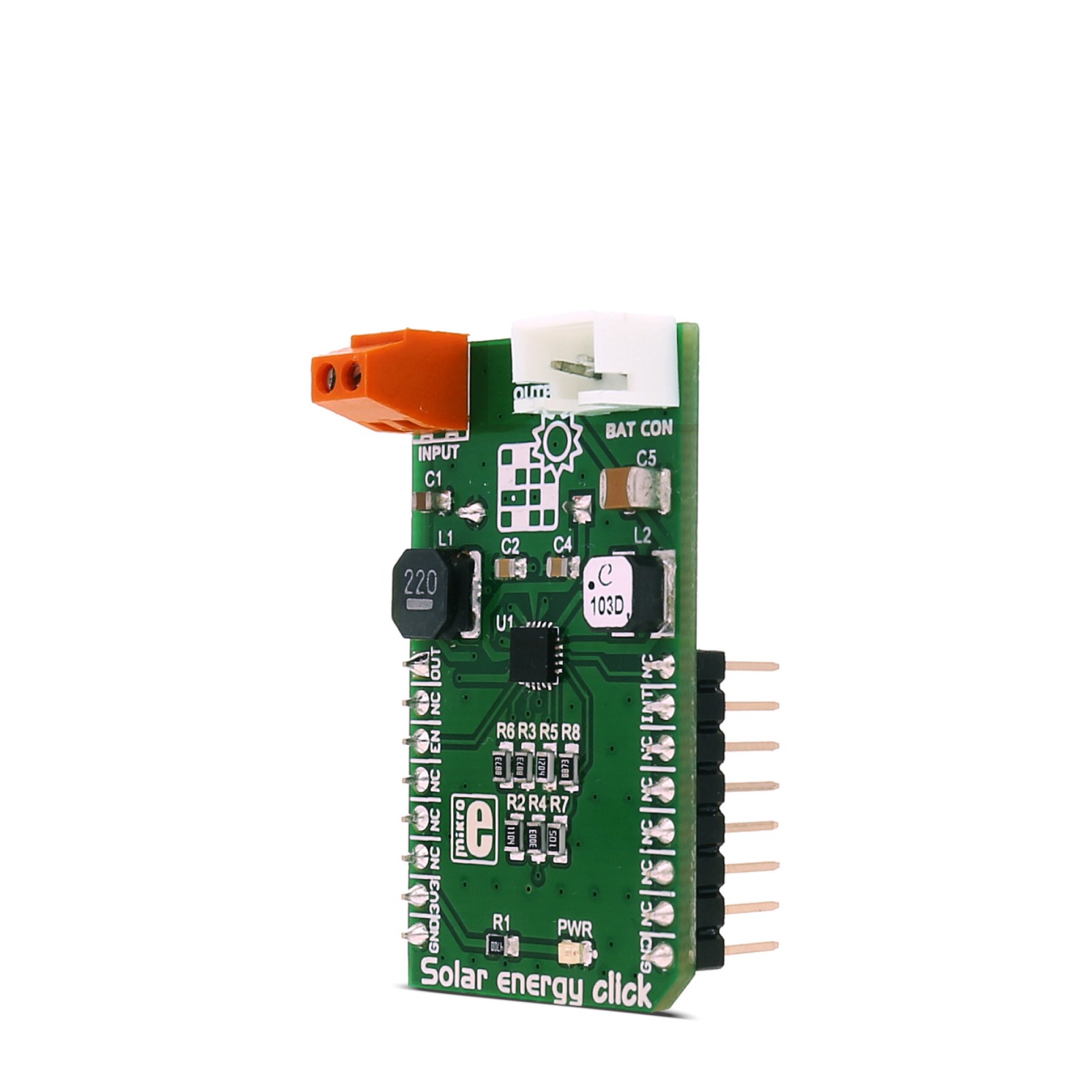
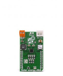
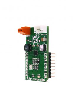
There are many battery chargers and solar energy harvesters out there already, but the Solar energy click has the unique feature – it encompasses both of these devices in a single package. The click uses Texas Instruments BQ25570 - a nano-power high-efficiency boost charger and buck converter device, designed to work with very low power energy harvesting elements, such as the photovoltaic and thermoelectric generators.
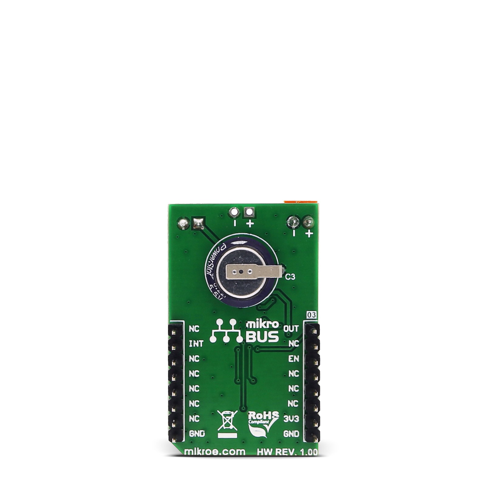
The Solar energy click recharges the connected LiPo battery or the onboard 220mF supercapacitor, using the photovoltaic element.This is done by utilizing the BQ25570’s charging and power harvesting capabilities and clever nano-power management features. This click can also power up low power consumption devices by using the stored energy, providing a way for continuous power operation of low power devices.
These features make the Solar energy click an ideal solution for powering wireless sensor networks, environment monitoring devices, portable and wearable health monitoring devices and similar low power self-sustained devices.
How does the click work?
The click is equipped with BQ25570, nano-power high-efficiency boost charger and buck converter device, designed to work with very low power energy harvesting elements. It can both provide power to the connected external load and charge the LiPo rechargeable battery using the solar panel as the photovoltaic element – employing its energy harvesting capabilities.
The connected load will be powered on either from the connected LiPo battery or the supercapacitor soldered on board. When the battery voltage drops under the 2.85V, the interrupt pin (routed to the mikroBUS™ INT pin) will be driven to a LOW logic state. The integrated nano-power management unit takes care of providing the proper charging conditions for the battery. When the battery is charged up to 3.25V – due to the hysteresis set with the voltage divider resistors – the INT pin will go to a HIGH logic state, once again. Also, thanks to the nano-power management unit, the battery will not get overcharged above 4.06V. The click board™ provides 2.6V/100mA for the connected external load on the output terminal.
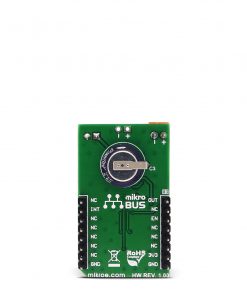
When the battery is not connected, the internal supercapacitor will be used as the energy storage element. This is useful for continuous powering up of very low power applications, as the supercapacitor should be able to provide power continuously since it will get recharged by the solar panel before it is drained out by the load. The internal converter will be disabled if the storage element voltage drops under the internally set under-voltage level of 1.95V, preventing the damage of completely draining out the connected storage element.
In addition to the INT pin, there are two more pins of the BQ25570 routed to the mikroBUS™, used to enable the BQ25570 internal sections (EN) and to enable the power output for the connected load (OUT). Setting the EN pin to the LOW logic level will enable the BQ25570 internal sections and the power charger features, while the HIGH logic level on the OUT pin will enable the power output for the connected load.
Specifications
Type
Battery charger,Solar Charger
Applications
Solar energy click is an ideal solution for powering wireless sensor networks, environment monitoring devices, portable and wearable health monitoring devices and similar low power self-sustained devices
On-board modules
Texas Instruments BQ25570 – a nano-power high-efficiency boost charger and buck converter device
Key Features
Provides power to the connected external load and charge the LiPo rechargeable battery using the solar panel, provides 2.6V/100mA for the connected external load on the output terminal, the battery will not get overcharged above 4.06V
Interface
GPIO
Feature
No ClickID
Compatibility
mikroBUS™
Click board size
M (42.9 x 25.4 mm)
Input Voltage
3.3V
Pinout diagram
This table shows how the pinout on Solar energy click corresponds to the pinout on the mikroBUS™ socket (the latter shown in the two middle columns).
Solar energy click electrical specifications
Description | Min | Typ | Max | Unit |
---|---|---|---|---|
Energy harvesting input terminal voltage rating | 0.1 | 5.1 | V | |
Energy harvesting input terminal power rating | 0.005 | 510 | mW |
Onboard settings and indicators
Label | Name | Default | Description |
---|---|---|---|
PWR | Power LED | – | Power LED indicates that the click is powered on |
Software support
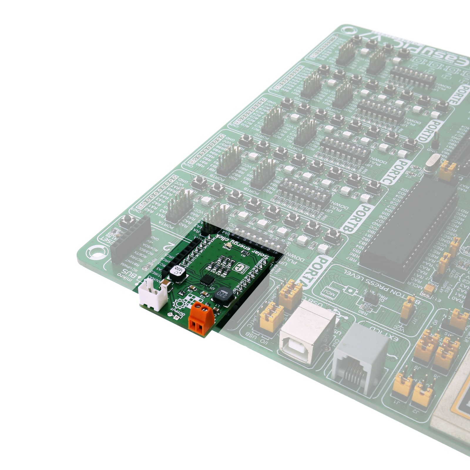
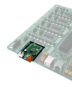
We provide an example for the Solar energy click on our LibStock page, as well as a demo application (example), developed using MikroElektronika compilers. The demo can run on all the main MikroElektronika development boards.
Examples Description
The application is composed of the following sections :
- System Initialization – Initializes GPIO pins used with SolarEnergy click and UART module used for data logging
- Application Initialization – Enables Solar energy click
- Application Task – (code snippet) Sequentially checks the state INT pin and reports current status by logging information to UART every 15 seconds.
void applicationTask() { Delay_ms( 15000 ); if (SOLAR_INT_PIN) { UART_Write_Text( "Battery in proper condition!"); UART_Write(13); UART_Write(10); } else { UART_Write_Text( "Battery voltage low"); UART_Write(13); UART_Write(10); } }
The example code for all architectures and compilers, and ready to use projects can be found on our LibStock page.
Other mikroE Libraries used in the example:
- UART
Additional notes and information
Depending on the development board you are using, you may need USB UART click, USB UART 2 click or RS232 click to connect to your PC, for development systems with no UART to USB interface available on the board. The terminal available in all Mikroelektronika compilers, or any other terminal application of your choice, can be used to read the message.