Subtotal: R1,050.00
Smart Mic Click
R405.00 ex. VAT
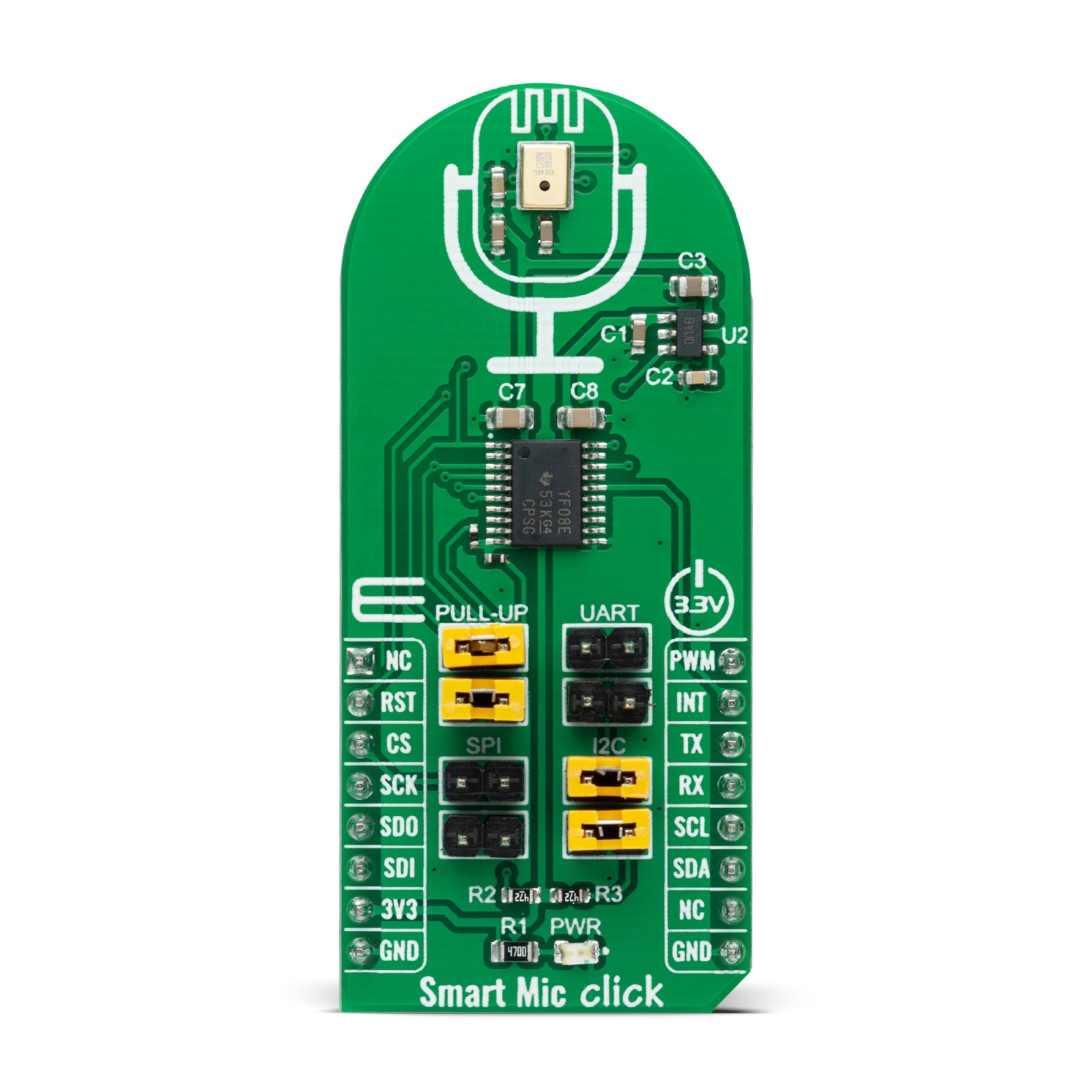
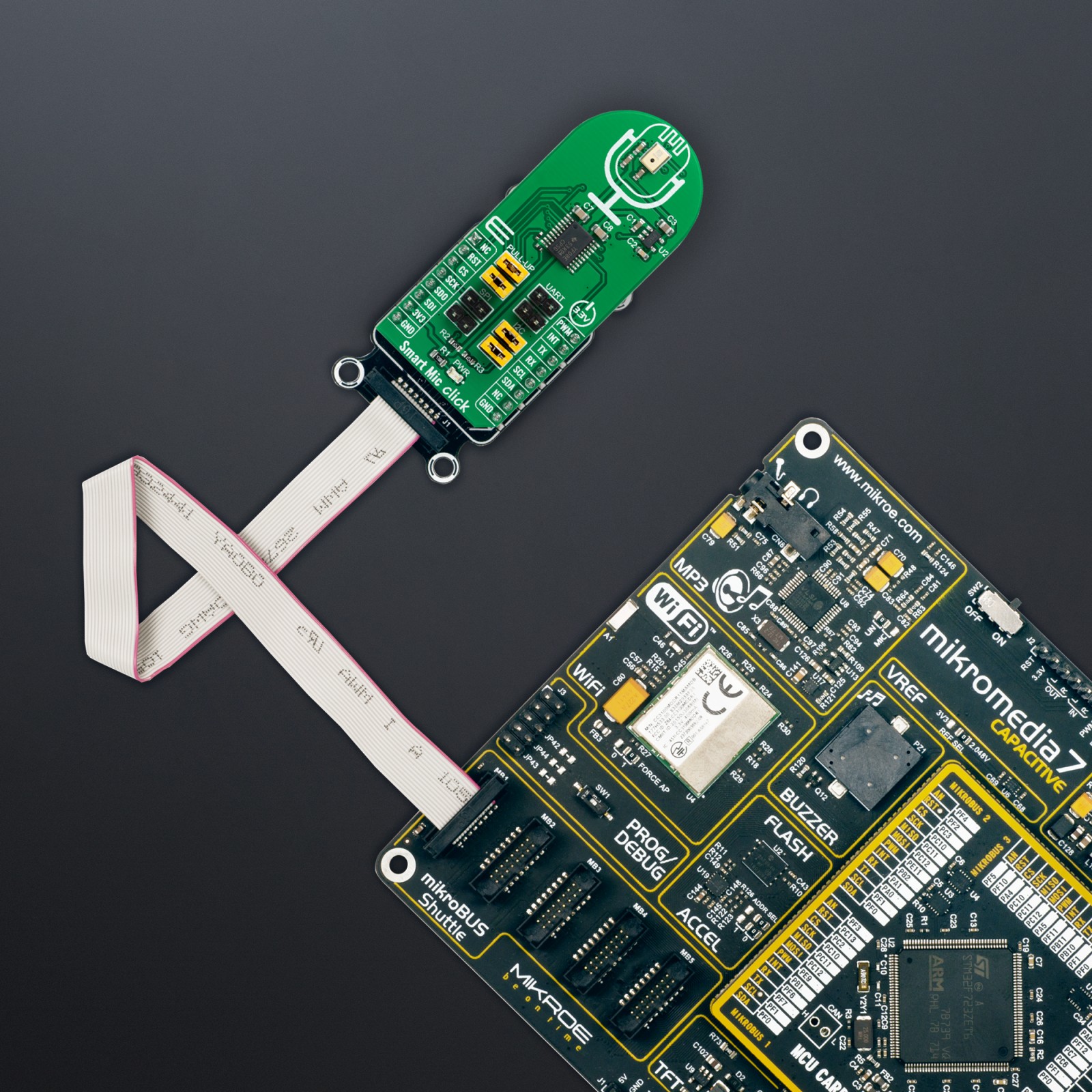
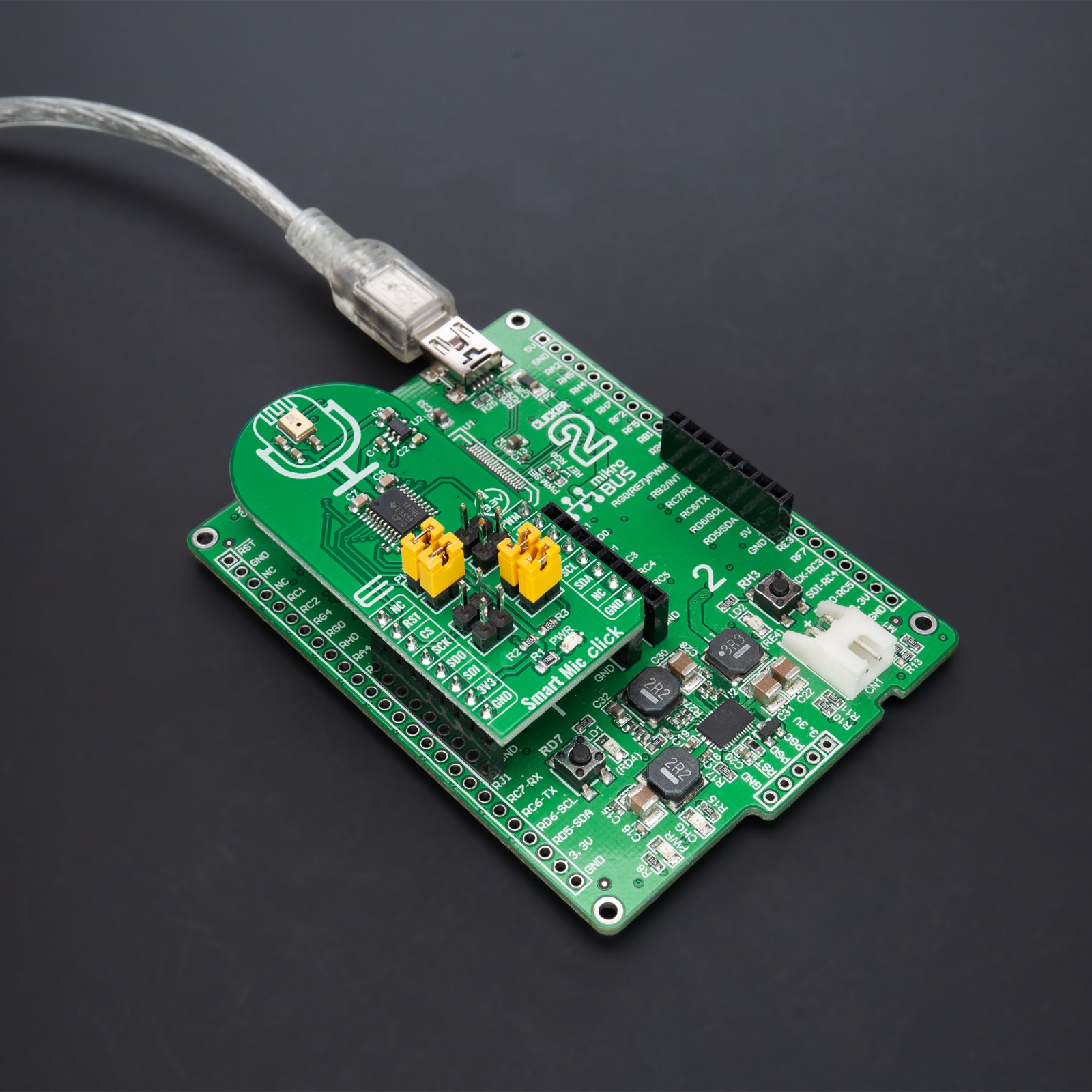
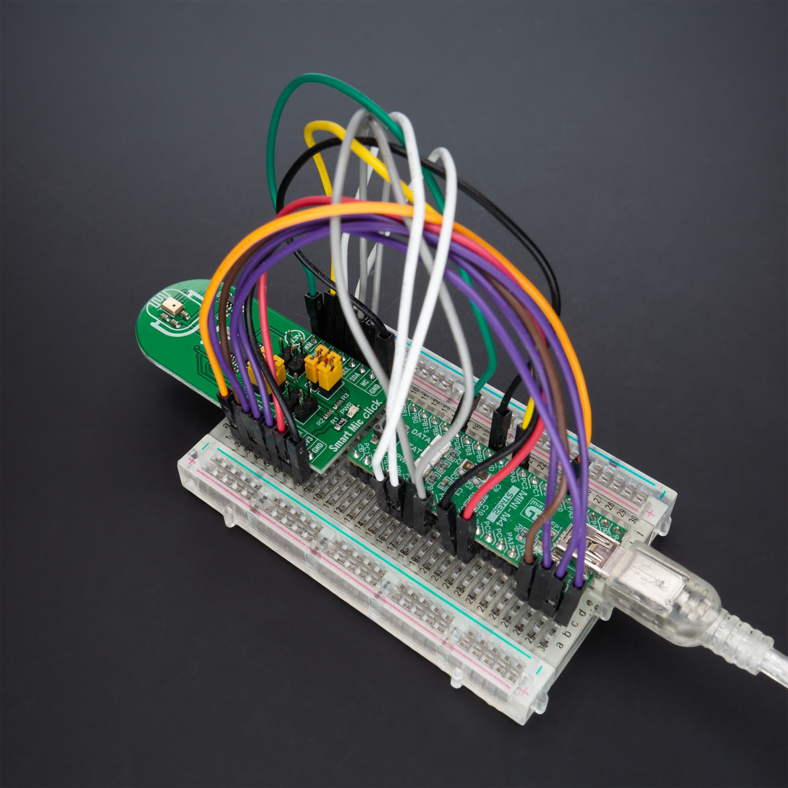
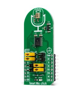
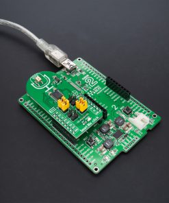
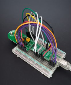
Smart Mic Click is a compact add-on board that provides wake-on-voice capabilities with secured privacy without compromising performance. This board features the IA611, an “Always-On” voice-wake acoustic processor from Knowles Electronics. The IA611 offers flexibility by supporting the most relevant audio and data interfaces and enables ultra-low-power voice and event detection, including voice UI supporting keywords, voice commands, and acoustic event detection. Its integrated programmable DSP is made available to 3rd party algorithms with 168kB of RAM, enabling unlimited creativity. This Click board™ represents an ideal solution to add a voice-enabled VUI or event detection into IoT products such as home sensors, appliances, lifestyle control devices, and security systems.
Smart Mic Click is supported by a mikroSDK compliant library, which includes functions that simplify software development. This Click board™ comes as a fully tested product, ready to be used on a system equipped with the mikroBUS™ socket.
Stock: Lead-time applicable.
| 5+ | R384.75 |
| 10+ | R364.50 |
| 15+ | R344.25 |
| 20+ | R331.29 |
How does it work?
Smart Mic Click as its foundation uses the IA611, a flexible, low-power, and highly integrated voice and audio processor system from Knowles Electronics. The IA611 includes an advanced Knowles audio-optimized DSP sub-system that has been designed to calculate intensive audio-processing algorithms with low power consumption. It also consists of a System Control Unit (SCU) that handles power management states such as sleep mode and generates internal clock signals. The IA611, “Always-On” Acoustic Processor, features a voice wake and voice ID keyword detector, a three-second buffer, and Knowles’ proven high-performance acoustic SiSonicTM MEMS technology in a single package.
.jpg)
The IA611 can be in one of the following operating modes. The Bootloader is a mode where after Power-Up, the IA611 waits for firmware download or use case setup. In Instruction mode, the IA611 is waiting for use case setup after firmware download, while in Open DSP Mode, the IA611 enables third-party algorithms. In Normal operational mode, the IA611 can be in software or hardware pass-through mode, which acts as a mic to the host.
The Voice Wake Mode allows low-power voice wake-up based on the detection of either a built-in keyword (OEM keyword), a user trained keyword (user keyword), or a user conditioned OEM keyword (Voice ID). In this mode, the IA611 monitors the microphone stream for acoustic activity, and when acoustic activity is detected, the IA611 automatically enters into a slightly higher power mode to analyze the speech utterance for the presence of the wake-up keyword. When a valid keyword is detected, the IA611 asserts an interrupt routed to the INT pin of the mikroBUS™ socket to trigger a complete system wake-up. If a keyword is not detected, the device returns to the ultra-low-power mode until the acoustic activity is detected again.
The IA611 implements various control interfaces, including UART, SPI, and an I2C slave interface with a control interface and audio interface port. Depending on the desired interface, the user needs to populate the selected jumper to activate that interface (SPI, I2C, or UART). Using an I2C interface, the user is given the option of additional activation of 4.7kΩ pull-up resistors on I2C lines, populating jumpers marked with PULL-UP.
The IA611 does not require a specific Power-Up sequence but requires a voltage of 1.8V for its supply and logic part to work correctly. Therefore, a small regulating LDO is used, the TC1015, providing a 1.8V out of 3.3V mikroBUS™ power rail, alongside Enable feature through the EN pin routed to the RST pin of the mikroBUS™ socket offering a switch operation to turn ON/OFF power delivery to the TC1015. Since the sensor for operation requires a power supply of 1.8V, this Click board™ also features the TXS0108E voltage-level translator. The interface lines are routed to the voltage-level translator allowing this Click board™ to work with 3.3V MCUs properly.
This Click board™ can be operated only with a 3.3V logic voltage level. The board must perform appropriate logic voltage level conversion before using MCUs with different logic levels. However, the Click board™ comes equipped with a library containing functions and an example code that can be used, as a reference, for further development.
Specifications
Type
Microphone
Applications
Can be used for a voice-enabled VUI or event detection into IoT products such as home sensors, appliances, lifestyle control devices, and security systems
On-board modules
IA611 – voice and audio processor system from Knowles Electronics
Key Features
Always-On Acoustic Processor, high accuracy voice wake and voice ID keyword recognition to wake-up system from a trigger phrase, various control interfaces and audio interface port, interrupt signal to the host when a Voice keyword trigger is detected, and more
Interface
I2C,SPI,UART
Feature
No ClickID
Compatibility
mikroBUS™
Click board size
L (57.15 x 25.4 mm)
Input Voltage
3.3V
Pinout diagram
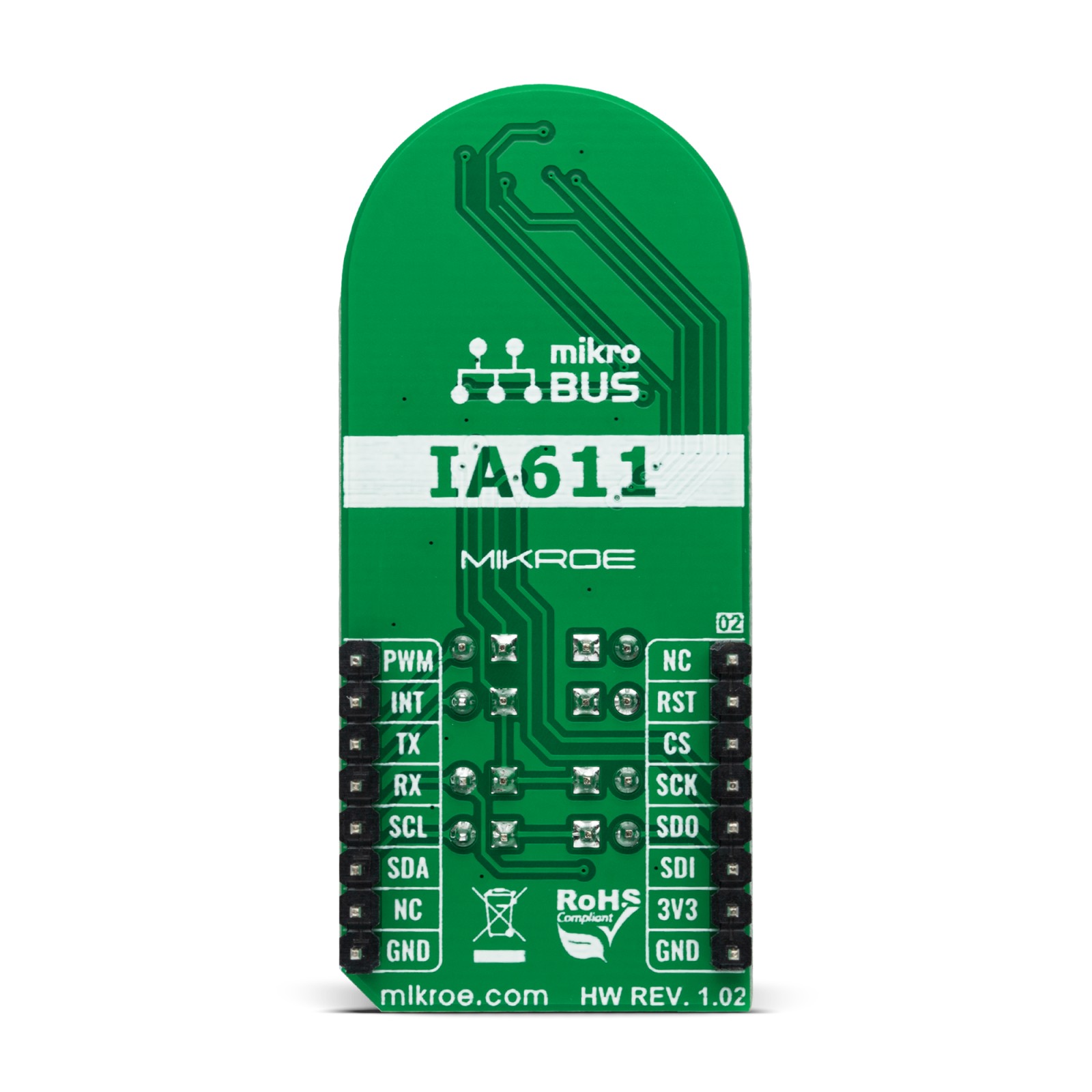
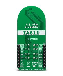
This table shows how the pinout on Smart Mic Click corresponds to the pinout on the mikroBUS™ socket (the latter shown in the two middle columns).
Onboard settings and indicators
| Label | Name | Default | Description |
|---|---|---|---|
| LD1 | PWR | – | Power LED Indicator |
| J1&J4 | UART | Unpopulated | UART Interface Jumpers |
| J2&J5 | I2C | Populated | I2C Interface Jumpers |
| J3&J6 | SPI | Unpopulated | SPI Interface Jumpers |
| J7&J8 | PULL-UP | Populated | I2C Interface Pull-Up Resistor Jumpers |
Smart Mic Click electrical specifications
| Description | Min | Typ | Max | Unit |
|---|---|---|---|---|
| Supply Voltage | – | 3.3 | – | V |
| Sensitivity | -38 | -37 | -36 | dBFS |
| Signal to Noise Ratio | – | -65.5 | – | dB |
| Bandwidth | – | 50 | – | kHz |
| Operating Temperature Range | -10 | +25 | +50 | °C |
Software Support
We provide a library for the Smart Mic Click as well as a demo application (example), developed using MikroElektronika compilers. The demo can run on all the main MikroElektronika development boards.
Package can be downloaded/installed directly from NECTO Studio Package Manager(recommended way), downloaded from our LibStock™ or found on Mikroe github account.
Library Description
This library contains API for Smart Mic Click driver.
Key functions
-
smartmic_wait_keywordThis function waits for a keyword event and then reads it and returns the keyword ID number. -
smartmic_download_keywordThis function downloads keyword models to the module. -
smartmic_voice_makeThis function performs voice make feature. It stops the route, then sets digital gain to 20db, sample rate to 16K, frame size to 16 ms, and finally it selects route 6 and configures algorithm parameters.
Example Description
This example demonstrates the use of Smart Mic Click board™ by programming it with 4 different keywords, and then waiting for a keyword event, parsing it and displaying on the USB UART.
void application_task ( void )
 {
     switch ( smartmic_wait_keyword ( &smartmic ) )
     {
         case SMARTMIC_OEM1_KWD_DETECTED:
         {
             log_printf ( &logger, " Hello VoiceQ keyword detected!rn" );
             break;
         }
         case SMARTMIC_OEM2_KWD_DETECTED:
         {
             log_printf ( &logger, " Switch The Light keyword detected!rn" );
             break;
         }
         case SMARTMIC_OEM3_KWD_DETECTED:
         {
             log_printf ( &logger, " Next Song keyword detected!rn" );
             break;
         }
         case SMARTMIC_OEM4_KWD_DETECTED:
         {
             log_printf ( &logger, " Baidu YiXia keyword detected!rn" );
             break;
         }
     }
 }
The full application code, and ready to use projects can be installed directly from NECTO Studio Package Manager(recommended way), downloaded from our LibStock™ or found on Mikroe github account.
Other Mikroe Libraries used in the example:
- MikroSDK.Board
- MikroSDK.Log
- Click.SmartMic
Additional notes and informations
Depending on the development board you are using, you may need USB UART click, USB UART 2 Click or RS232 Click to connect to your PC, for development systems with no UART to USB interface available on the board. UART terminal is available in all MikroElektronika compilers.
mikroSDK
This Click board™ is supported with mikroSDK – MikroElektronika Software Development Kit. To ensure proper operation of mikroSDK compliant Click board™ demo applications, mikroSDK should be downloaded from the LibStock and installed for the compiler you are using.
For more information about mikroSDK, visit the official page.
Resources
Downloads
| Weight | 20 g |
|---|---|
| Brand | MikroElektronika |

 DAC Click
  MP3 Click
  Proximity Click