 DAC Click
 Subtotal: R395.00


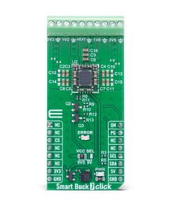
Smart Buck 7 Click
R885.00 ex. VAT
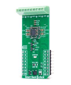
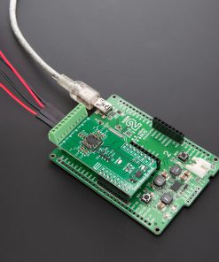
Smart Buck 7 Click is a compact add-on board designed to provide four precisely regulated power rails from a single external source, ideal for powering complex embedded systems with multiple voltage domains. It is based on the MYWGC3R53FF, a MonoBK™ multi-output DC-DC converter module from Murata. This highly integrated module delivers fixed output voltages of 1.2V, 1.8V, 2.5V, and 3.3V with a total combined output power of up to 15.2W, using a synchronous buck topology for high efficiency. It supports I2C communication up to 400kHz, features ON/OFF control, a Power Good (PG) indicator, and protection mechanisms including UVLO, OCP, OVP, OTP, and short-circuit protection. It is ideally suited for powering FPGAs, CPUs, and other programmable logic or mixed-voltage systems in telecom, datacom, and industrial applications.
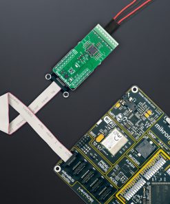
Smart Buck 7 Click is fully compatible with the mikroBUS™ socket and can be used on any host system supporting the mikroBUS™ standard. It comes with the mikroSDK open-source libraries, offering unparalleled flexibility for evaluation and customization. What sets this Click board™ apart is the groundbreaking ClickID feature, enabling your host system to automatically detect and identify this add-on board.
Stock: Lead-time applicable.
| 5+ | R840.75 |
| 10+ | R796.50 |
| 15+ | R752.25 |
| 20+ | R723.93 |
How does it work?
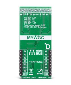
Smart Buck 7 Click is based on the MYWGC3R53FF, a MonoBK™ multi-output DC-DC converter module from Murata, providing multiple precisely regulated output voltages from a single power source. The MYWGC3R53FF accepts an external input voltage ranging from 4.3V to 5.5V applied to the VEXT terminal, with a maximum input current of 3.45A, and uses a fixed-frequency synchronous buck converter topology to derive four independent, fully regulated output rails: 1.2V at 2.5A (Terminal 1V2), 1.8V at 1A (Terminal 1V8), 2.5V at 1.5A (Terminal 2V5), and 3.3V at 2A (Terminal 3V3), delivering a combined total power output of up to 15.2W. This Click board™ is ideal for applications such as powering FPGAs, CPUs, programmable logic, and systems utilizing Distributed Bus Architectures (DBA), as well as complex mixed-voltage platforms commonly found in datacom and telecom infrastructures.
The MYWGC3R53FF interfaces with the host MCU via an I2C-compatible serial interface operating at standard (100kHz) or fast mode (400kHz) clock speeds, enabling control and monitoring of output voltages and status registers. A dedicated ON pin allows for external enable/disable control of the entire power module, supporting power domain management in software-controlled power sequencing scenarios. Additionally, the MYWGC3R53FF features a Power Good (PG pin) output that is also routed to an onboard red LED labeled ERROR, which provides real-time visual indication of any voltage irregularities or faults – when one or more output voltages are out of regulation or disabled.
System protection is ensured by an integrated suite of safety mechanisms, including under-voltage lockout (UVLO) to prevent operation below the minimum input threshold, output short-circuit protection for fault containment, over-current protection (OCP) to prevent damage from excessive load conditions, over-voltage protection (OVP) to guard against feedback failure or load disconnects, and over-temperature protection (OTP) that triggers thermal shutdown to maintain device reliability and system integrity.
This Click board™ can operate with either 3.3V or 5V logic voltage levels selected via the VCC SEL jumper. This way, both 3.3V and 5V capable MCUs can use the communication lines properly. Also, this Click board™ comes equipped with a library containing easy-to-use functions and an example code that can be used as a reference for further development.
Specifications
Type
Buck
Applications
Ideal for powering FPGAs, CPUs, and other programmable logic or mixed-voltage systems in telecom, datacom, and industrial applications
On-board modules
MYWGC3R53FF – MonoBK™ multi output DC-DC converter from Murata
Key Features
Four independent fixed output rails, total output power of up to 15.2W, high-efficiency synchronous buck converter topology, I2C interface, ON/OFF control, Power Good output with visual LED indicator, under-voltage lockout (UVLO), output short-circuit protection, over-current protection (OCP), over-voltage protection (OVP), over-temperature protection (OTP), and more
Interface
GPIO,I2C
Feature
ClickID
Compatibility
mikroBUS™
Click board size
L (57.15 x 25.4 mm)
Input Voltage
3.3V or 5V,External
Pinout diagram
This table shows how the pinout on Smart Buck 7 Click corresponds to the pinout on the mikroBUS™ socket (the latter shown in the two middle columns).
| Notes | Pin | Pin | Notes | ||||
|---|---|---|---|---|---|---|---|
| NC | 1 | AN | PWM | 16 | ON | Device Enable | |
| NC | 2 | RST | INT | 15 | PG | Power-Good Indicator | |
| ID COMM | CS | 3 | CS | RX | 14 | NC | |
| NC | 4 | SCK | TX | 13 | NC | ||
| NC | 5 | MISO | SCL | 12 | SCL | I2C Clock | |
| NC | 6 | MOSI | SDA | 11 | SDA | I2C Data | |
| Power Supply | 3.3V | 7 | 3.3V | 5V | 10 | 5V | Power Supply |
| Ground | GND | 8 | GND | GND | 9 | GND | Ground |
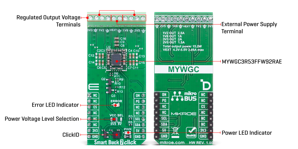
Onboard settings and indicators
| Label | Name | Default | Description |
|---|---|---|---|
| LD1 | PWR | – | Power LED Indicator |
| LD2 | ERROR | – | Error LED Indicator |
| JP1 | VCC SEL | Left | Power Voltage Level Selection 3V3/5V: Left position 3V3, Right position 5V |
Smart Buck 7 Click electrical specifications
| Description | Min | Typ | Max | Unit |
|---|---|---|---|---|
| Supply Voltage | 3.3 | – | 5 | V |
| External Power Supply Terminal | 4.3 | – | 5.5 | V |
| Output Voltage | 1.2 / 1.8 / 2.5 / 3.3 | V | ||
| Output Current | 2.5 / 1 / 1.5 / 2 | A | ||
| Total Output Power | – | – | 15.2 | W |
Software Support
Smart Buck 7 Click demo application is developed using the NECTO Studio, ensuring compatibility with mikroSDK‘s open-source libraries and tools. Designed for plug-and-play implementation and testing, the demo is fully compatible with all development, starter, and mikromedia boards featuring a mikroBUS™ socket.
Example Description
This example demonstrates the use of the Smart Buck 7 Click board. The application cyclically enables different combinations of the four buck converter outputs (1.2V, 1.8V, 2.5V, and 3.3V) and logs which outputs are currently active. It also monitors the PG (Power Good) pin and logs any fault conditions, including undervoltage and over-temperature events.
Key Functions
smartbuck7_cfg_setupThis function initializes Click configuration structure to initial values.smartbuck7_initThis function initializes all necessary pins and peripherals used for this Click board.smartbuck7_default_cfgThis function executes a default configuration of Smart Buck 7 Click board.smartbuck7_get_pg_pinThis function reads the logic level of the PG pin.smartbuck7_enable_buckThis function enables one or more buck regulators by setting their control bits.smartbuck7_disable_buckThis function disables one or more buck regulators by clearing their control bits.
Application Init
Initializes the logger and the Smart Buck 7 Click driver, and applies the default configuration.
Application Task
Cycles through various buck output combinations, logs the enabled outputs, checks the PG pin for fault indication, and logs any detected fault status.
Application Output
This Click board can be interfaced and monitored in two ways:
- Application Output – Use the “Application Output” window in Debug mode for real-time data monitoring. Set it up properly by following this tutorial.
- UART Terminal – Monitor data via the UART Terminal using a USB to UART converter. For detailed instructions, check out this tutorial.
Additional Notes and Information
The complete application code and a ready-to-use project are available through the NECTO Studio Package Manager for direct installation in the NECTO Studio. The application code can also be found on the MIKROE GitHub account.
Resources
Downloads
| Weight | 22 g |
|---|---|
| Brand | MikroElektronika |