How does it work?
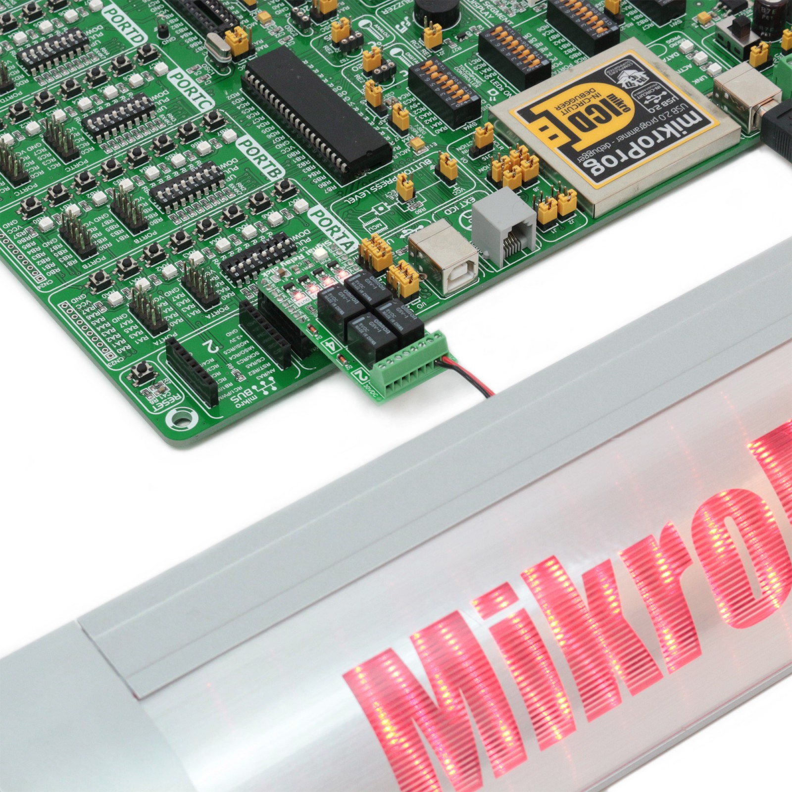
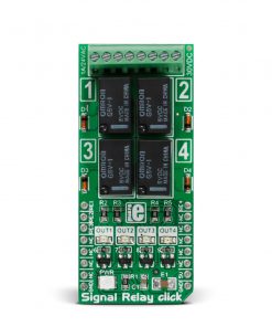
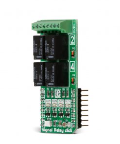
Signal Relay Click is based on four G5V-1s, an ultra-miniature, highly sensitive single-pole double-throw (SPDT) relays for signal circuits from Omron. The G5V-1 relays feature wide switching power of up to 1A, high sensitivity with 150mW of nominal coil power consumption, and are of fully-sealed construction, thus offering environmental resistance. The relay internal single-type contact is made as a single crossbar of gold and silver alloy. The relay output markings of the screw terminal are labeled at the bottom of this Click board™ with additional info. Every relay has its LED for visual presentation, labeled OUT1-4.
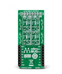
To communicate with the host microcontroller, the Signal Relay Click uses four mikroBUS™ pins labeled RE1, RE2, RE3, and RE4. All relays are driven through small amplifier transistors as a safe solution for the relays’ current and their impact on the host MCU. The Signal Relay Click also features small signal fast switching diodes on each relay to prevent electrical noise. One thing to note, the relays’ coils are 5-volts driven.
This Click board™ can only be operated with a 5V logic voltage level. The board must perform appropriate logic voltage level conversion before using MCUs with different logic levels. However, the Click board™ comes equipped with a library containing functions and an example code that can be used as a reference for further development.
Specifications
Type
Relay
Applications
Can be used for the development of ON/OFF control in various home automation devices, like alarm units, lamps, heaters, or for energizing coils of bigger relays and contactors in industrial AC schemes (12/24V)
On-board modules
G5V-1 – single-pole double-throw (SPDT) relay from Omron
Key Features
Power switching from 1mA to 1A, maximum contact resistance 100mΩ, 150mW nominal coil power consumption, four independent driven signal relays with screw terminal with 2-pins for each, 5 volts driven coils, and more
Interface
GPIO
Feature
No ClickID
Compatibility
mikroBUS™
Click board size
L (57.15 x 25.4 mm)
Input Voltage
5V
Pinout diagram
This table shows how the pinout on Signal Relay Click corresponds to the pinout on the mikroBUS™ socket (the latter shown in the two middle columns).
Onboard settings and indicators
Label | Name | Default | Description |
---|---|---|---|
LD1 | PWR | – | Power LED Indicator |
LD2-LD5 | OUT1-OUT4 | – | Relay ON/OFF LED Indicator |
Signal Relay Click electrical specifications
Description | Min | Typ | Max | Unit |
---|---|---|---|---|
Supply Voltage | – | 5 | – | V |
Coil Voltage | – | 5 | – | V |
Coil Resistance | – | 167 | – | Ω |
Switching AC Voltage | – | 24 | – | VDC |
Switching DC Voltage | – | 30 | – | VDC |
Switching Current | – | 1 | V |
Software Support
We provide a library for the Signal Realy Click as well as a demo application (example), developed using MIKROE compilers. The demo can run on all the main MIKROE development boards.
Package can be downloaded/installed directly from NECTO Studio Package Manager (recommended), downloaded from our LibStock™ or found on Mikroe github account.
Library Description
This library contains API for Signal Realy Click driver.
Key functions
- Relays state
Example Description
Demo application is used to shows basic controls Signal Relay click.
void application_task ( void )
{
uint8_t cnt;
// Task implementation.
for ( cnt = 1; cnt <= 4; cnt++ )
{
log_info( &logger, " *** Relay [ %d ] ON ", cnt );
signalrelay_relay_state( &signalrelay, cnt, SIGNALRELAY_STATE_ON );
Delay_ms( 200 );
log_info( &logger, " *** Relay [ %d ] OFF ", cnt );
signalrelay_relay_state( &signalrelay, cnt, SIGNALRELAY_STATE_OFF );
Delay_ms( 200 );
}
}
The full application code, and ready to use projects can be installed directly from NECTO Studio Package Manager (recommended), downloaded from our LibStock™ or found on Mikroe github account.
Other Mikroe Libraries used in the example:
- MikroSDK.Board
- MikroSDK.Log
- Click.SignalRealy
Additional notes and informations
Depending on the development board you are using, you may need USB UART click, USB UART 2 Click or RS232 Click to connect to your PC, for development systems with no UART to USB interface available on the board. UART terminal is available in all MIKROE compilers.
mikroSDK
This Click board™ is supported with mikroSDK – MIKROE Software Development Kit. To ensure proper operation of mikroSDK compliant Click board™ demo applications, mikroSDK should be downloaded from the LibStock and installed for the compiler you are using.
For more information about mikroSDK, visit the official page.