


Shutter Click
R255.00 ex. VAT
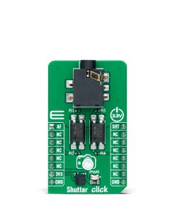
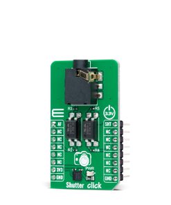
Shutter Click is an adapter Click board™ that can be used to implement an automated capturing function. This Click board™ has one 3.5mm jack connector suitable for a camera connection with which the frame is captured. By combining two mikroBUS™ pins and the VO617A, a high-reliability phototransistor from Vishay Semiconductors used as a camera activation switch, activating the camera’s Auto-Focus and the action of taking pictures is realized. This Click board™ allows you to expressly capture frames in a simple way for various types of photographic and security applications to capture those parts you need.
Shutter Click is fully compatible with the mikroBUS™ socket and can be used on any host system supporting the mikroBUS™ standard. It comes with the mikroSDK open-source libraries, offering unparalleled flexibility for evaluation and customization. What sets this Click board™ apart is the groundbreaking ClickID feature, enabling your host system to seamlessly and automatically detect and identify this add-on board.
Stock: Lead-time applicable.
| 5+ | R242.25 |
| 10+ | R229.50 |
| 15+ | R216.75 |
| 20+ | R208.59 |
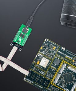
NOTE: A 3.5mm remote shutter cable with C3 connecting cord is used for this board’s testing. In addition to this type of connecting cord, this Click board™ is also compatible with other cords, such as C1, N1, N3, and S2 for various cameras such as Canon, Nikon, Sony, and others.
How does it work?
Shutter Click is an adapter Click board™ that simplifies the camera’s use for capturing a photo at a precise moment. This Click board™ represents a small PCB connected to the mikroBUS™ socket like any other Click board™, with a 3.5mm jack connector used for the camera connection. Using two pins of the mikroBUS™ socket and a high-reliability phototransistor, the VO617A from Vishay Semiconductors enables a remote control input used to focus and trigger the camera shutter.

This Click board™ allows users to upgrade their projects with a solution capable of capturing frames you need at the exact moment in a simple way for various types of applications. This phototransistor VO617A has a GaAs infrared diode emitter, which is optically coupled to a silicon planar phototransistor detector. As already mentioned, two signals are everything you need for the operation: the AF and SHT routed to the AN and PWM pins of the mikroBUS™ socket to enable the camera’s Auto-Focus mode and the action of taking pictures. Setting a high logic state on the AF pin activates Auto-Focus mode, while a low logic level disables it. The same policy applies to the shutter trigger function.
This Click board™ can be operated only with a 3.3V logic voltage level. The board must perform appropriate logic voltage level conversion before using MCUs with different logic levels. However, the Click board™ comes equipped with a library containing functions and an example code that can be used as a reference for further development.
Specifications
Type
Adapter
Applications
Can be used to expressly capture frames in various photographic and security applications
On-board modules
VO617A – high-reliability phototransistor from Vishay Semiconductors
Key Features
Automated capturing feature, easy control, high reliability phototransistor, low power consumption, Auto-Focus and Shutter trigger mode, and more
Interface
GPIO
Feature
ClickID
Compatibility
mikroBUS™
Click board size
M (42.9 x 25.4 mm)
Input Voltage
3.3V
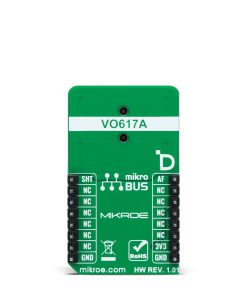
Pinout diagram
This table shows how the pinout on Shutter Click corresponds to the pinout on the mikroBUS™ socket (the latter shown in the two middle columns).
| Notes | Pin | Pin | Notes | ||||
|---|---|---|---|---|---|---|---|
| Auto-Focus | AF | 1 | AN | PWM | 16 | SHT | Shutter Trigger |
| NC | 2 | RST | INT | 15 | NC | ||
| ID COMM | CS | 3 | CS | RX | 14 | NC | |
| NC | 4 | SCK | TX | 13 | NC | ||
| NC | 5 | MISO | SCL | 12 | NC | ||
| NC | 6 | MOSI | SDA | 11 | NC | ||
| Power Supply | 3.3V | 7 | 3.3V | 5V | 10 | NC | |
| Ground | GND | 8 | GND | GND | 9 | GND | Ground |
Onboard settings and indicators
| Label | Name | Default | Description |
|---|---|---|---|
| LD1 | PWR | – | Power LED Indicator |
Shutter Click electrical specifications
| Description | Min | Typ | Max | Unit |
|---|---|---|---|---|
| Supply Voltage | – | 3.3 | – | V |
Software Support
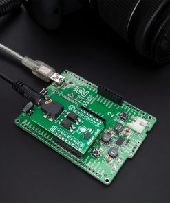
Shutter Click demo application is developed using the NECTO Studio, ensuring compatibility with mikroSDK‘s open-source libraries and tools. Designed for plug-and-play implementation and testing, the demo is fully compatible with all development, starter, and mikromedia boards featuring a mikroBUS™ socket.
Example Description
This example demonstrates the use of Shutter Click board by taking pictures with and without auto focus function.
Key Functions
shutter_cfg_setupConfig Object Initialization function.shutter_initInitialization function.shutter_set_auto_focusThis function sets the auto focus ON/OFF by setting the AF pin to desired logic state.shutter_set_shutterThis function sets the shutter ON/OFF by setting the SHT pin to desired logic state.shutter_take_pictureThis function sets AF and SHT pins to desired states for taking pictures with or without auto focus function.
Application Init
Initializes the driver and logger.
Application Task
Swithes ON the auto focus function and triggers the shutter to take the picture, then swithes OFF the auto focus and triggers the shutter. The shutter is triggered every 13 seconds approximately. All data is being logged on the USB UART where you can track the program flow.
Application Output
This Click board can be interfaced and monitored in two ways:
- Application Output – Use the “Application Output” window in Debug mode for real-time data monitoring. Set it up properly by following this tutorial.
- UART Terminal – Monitor data via the UART Terminal using a USB to UART converter. For detailed instructions, check out this tutorial.
Additional Notes and Information
The complete application code and a ready-to-use project are available through the NECTO Studio Package Manager for direct installation in the NECTO Studio. The application code can also be found on the MIKROE GitHub account.
Resources
Downloads
| Weight | 19 g |
|---|---|
| Brand | MikroElektronika |