How does it work?
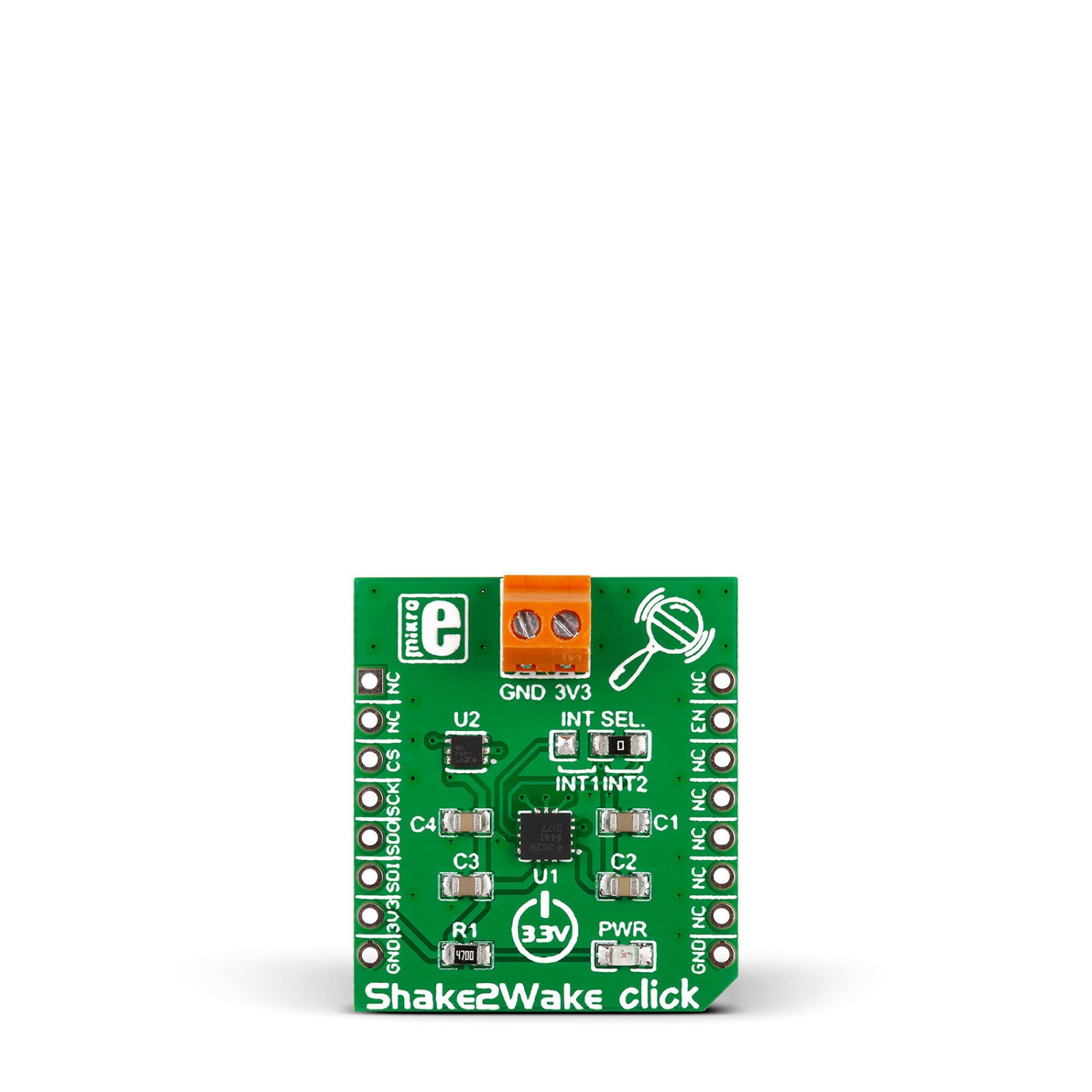
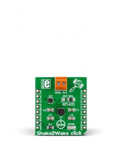
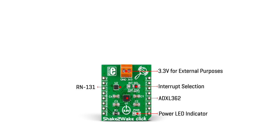
Shake2Wake Click is based on the ADXL362, a digital output 3-axis MEMS accelerometer, and the ADP195, a logic-controlled high-side power switch with reverse current blocking, both from Analog Devices. The ultralow-power ADXL362 features an on-chip temperature sensor, a high resolution of 1mg/LSB detection with ranges of ±2 g, ±4 g, and ±8, low noise, and acceleration sample synchronization via an external trigger. The ADXL362 comes with various features for system-level power savings, such as adjustable thresholds for motion activation, autonomous interrupt processing without the need for the host MCU intervention that allows the rest of the system to be turned off completely, deep embedded FIFO, and more. The ADXL362 also provides a 12-bit output resolution and 8-bit data for more efficient single-byte transfers when a lower resolution is sufficient.
This Click board™ has two main operating modes: measuring and wake-up. For use as a regular accelerometer, for continuous sensing, use the measurement mode. The ADP195 on this Click board™ serves as an onboard power switch that controls an external device connected through a screw terminal. The load switch isolates the power domain and protects against the reverse current flow from output to input.
The ADXL362 uses an SPI serial interface to communicate with the host microcontroller. Several of the built-in functions of the ADXL362 can trigger interrupts to alert the host MCU of certain status conditions. The ADXL362 can use INT1 or INT2 selected over the INT SEL jumper to meet the mapped condition expected to be activated, with INT2 chosen by default. The ADXL362’s interrupt is also connected to the host MCU over the INT pin, enabling the ADP195 when movement occurs.
This Click board™ can be only operated with a 3.3V logic voltage level. The board must perform appropriate logic voltage level conversion before using MCUs with different logic levels. However, the Click board™ comes equipped with a library containing functions and an example code that can be used, as a reference, for further development.
Specifications
Type
Acceleration,Motion
Applications
Can be used for designing accelerometer-based motion-activated devices, but also, it can be used as a regular accelerometer for continuous sensing.
On-board modules
ADXL362 – digital output 3-axis MEMS accelerometer from Analog Devices
ADP195 – logic controlled high-side power switch with reverse current blocking from Analog Devices
Key Features
3-axis detection, movement activation of the onboard power switch, two main operating modes: measuring and wake-up, SPI interface, low power consumption, and more
Interface
GPIO,SPI
Feature
No ClickID
Compatibility
mikroBUS™
Click board size
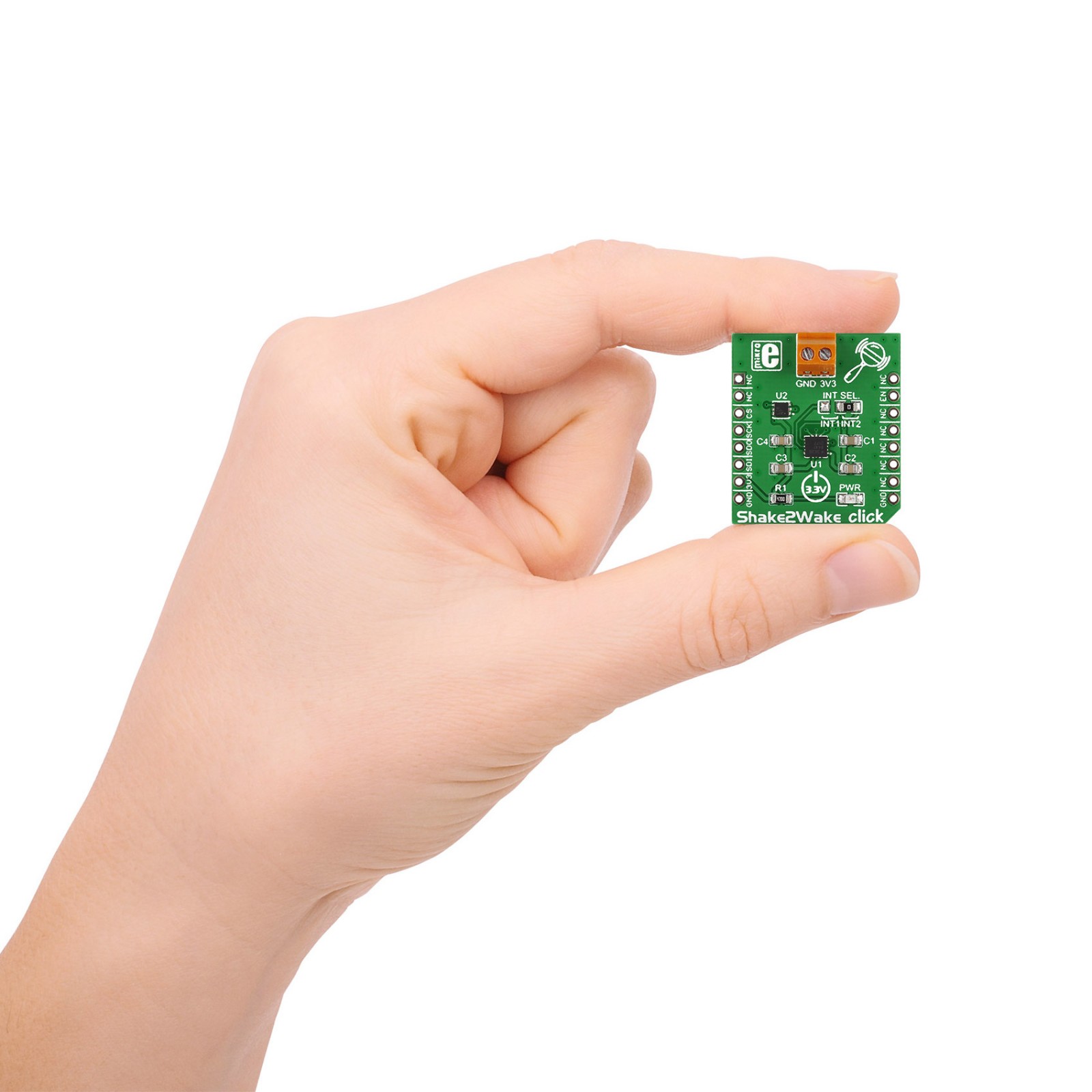
S (28.6 x 25.4 mm)
Input Voltage
3.3V
Pinout diagram
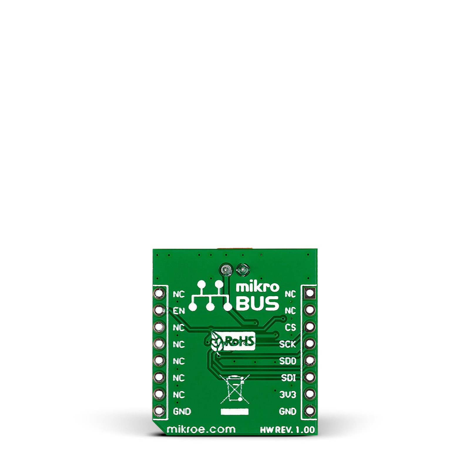
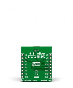
This table shows how the pinout on Shake2Wake Click corresponds to the pinout on the mikroBUS™ socket (the latter shown in the two middle columns).
Onboard settings and indicators
Label | Name | Default | Description |
---|---|---|---|
LD1 | PWR | – | Power LED Indicator |
JP1 | INT SEL | Right | Interrupt Selection INT1/INT2: Left position INT1, Right position INT2 |
Shake2Wake Click electrical specifications
Description | Min | Typ | Max | Unit |
---|---|---|---|---|
Supply Voltage | – | 3.3 | – | V |
Accelerometer Sensitivity | 1 | – | 4 | mg/LSB |
Accelerometer Range | ±2 | – | ±8 | g |
Software Support
We provide a library for the Shake2Wake Click as well as a demo application (example), developed using Mikroe compilers. The demo can run on all the main Mikroe development boards.
Package can be downloaded/installed directly from NECTO Studio Package Manager (recommended), downloaded from our LibStock™ or found on Mikroe github account.
Library Description
This library contains API for Shake2Wake Click driver.
Key functions
-
This function is used to read 8-bit acceleration data per axis.
-
This function is used to read the 3-axis raw data from the accelerometer.
-
This function is used to enable FIFO and mode selection.
Example Description
This app shows the capabilities of the Shake2Wake click by reading values of an accelerometer.
void application_task ( void )
{
uint8_t temp_val;
float temperature;
int16_t x_val;
int16_t y_val;
int16_t z_val;
shake2wake_get_raw_data( &shake2wake, &x_val, &y_val, &z_val );
temperature = shake2wake_read_temperature( &shake2wake );
log_printf( &logger, "X axis: %drn", x_val );
log_printf( &logger, "Y axis: %drn", y_val );
log_printf( &logger, "Z axis: %drn", z_val );
log_printf( &logger, "Temperature: %f rn", temperature );
log_printf( &logger, "--------------------------rn" );
Delay_ms( 1000 );
}
The full application code, and ready to use projects can be installed directly from NECTO Studio Package Manager (recommended), downloaded from our LibStock™ or found on Mikroe github account.
Other Mikroe Libraries used in the example:
- MikroSDK.Board
- MikroSDK.Log
- Click.Shake2Wake
Additional notes and informations
Depending on the development board you are using, you may need USB UART click, USB UART 2 Click or RS232 Click to connect to your PC, for development systems with no UART to USB interface available on the board. UART terminal is available in all Mikroe compilers.
mikroSDK
This Click board™ is supported with mikroSDK – Mikroe Software Development Kit, that needs to be downloaded from the LibStock and installed for the compiler you are using to ensure proper operation of mikroSDK compliant Click board™ demo applications.
For more information about mikroSDK, visit the official page.